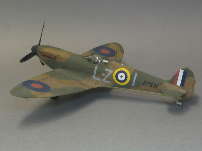
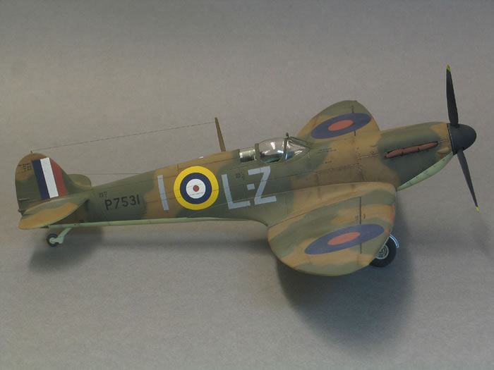
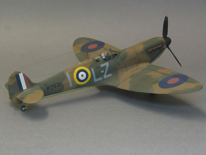
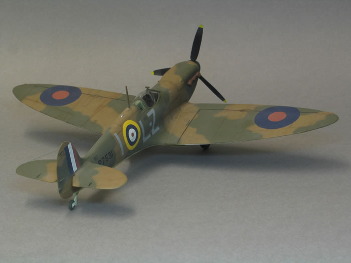
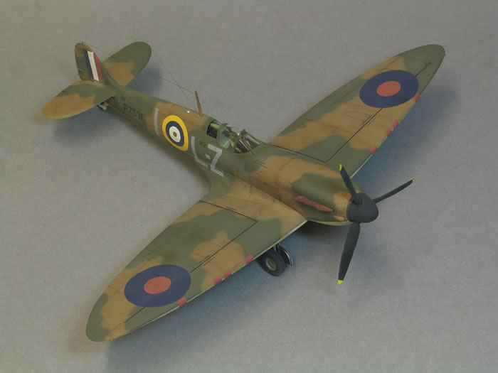
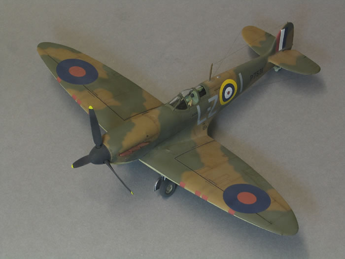
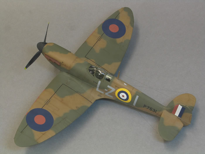
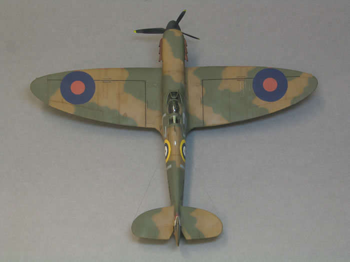
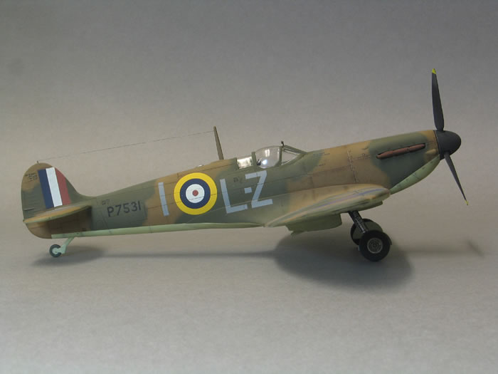
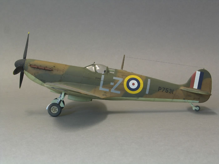
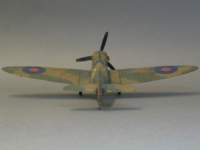
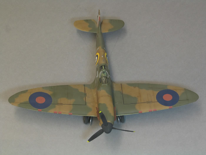
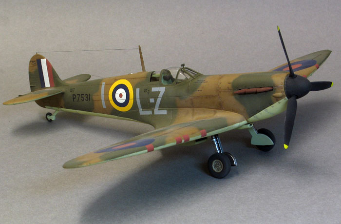
Airfix 1/48 scale
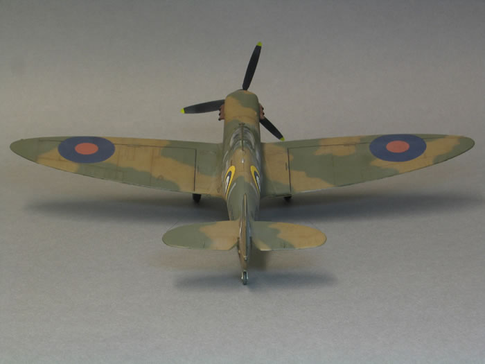
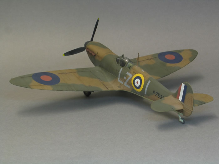
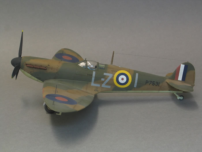
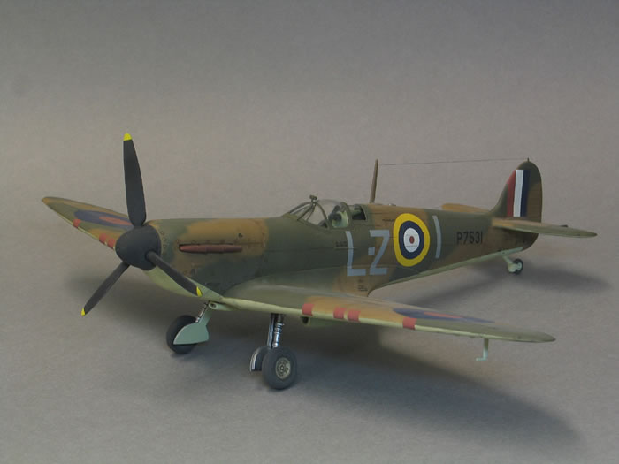
Supermarine Spitfire Mk.IIa
by Steven Budd
|
Supermarine Spirfire Mk.IIa |

Airfix's 1/48 scale Spitfire Mk.I is avaiable online from Squadron.com
Has there ever been an aircraft type modelled in plastic that has been more heavily scrutinised with each release than Mitchell’s Spitfire?
It seems that the many compound and subtle curves of this quintessentially British and uniquely beautiful aircraft have taxed the abilities of toolmakers to the limit and beyond. Launching a Spit at the modelling public has become something of a white knuckle experience for manufacturers, as they brace themselves each time for the jury’s decision on their product. Do I wish Eduard would join in and do a ‘definitive’ series of them? Oh yes.
With four Tamiya Mk Is already parked in the loft I wasn’t in the market for another. I’d already chatted to the staff in Hannants about the new Airfix Mk I and decided, mainly because the tail looked a little small, to give it a miss and stick with the big T. My resistance was soon dissolved some weeks later however, after some talk about the kit here as well as Brett’s full build of an early Mk I elsewhere on the site.
I pulled one off the shelf on a whim as much as anything, while I was buying modelling supplies in Hobbycraft. By this time the feedback machine had indicated the need for a wing root fix, along with the tail shape, chunky door hinge and trim actuators, thick trailing edges and Rotol prop . It’s always an advantage to have the benefit of someone else’s experience in nailing a kit together of course and in view of Brett’s build was tempted into seeing if I could also tackle these issues successfully.
On the up side, the basic shapes (tail excepted) seemed very good and the plastic looked to be on the softer side, a personal preference. Panel lines on my example varied a bit from deep-ish to quite fine and overall looked promising.
So why do a Mk IIa when the early Mk I’s on the box lid? Nothing more than simple, personal aesthetics – I personally prefer the Mk IIa lines over the other option.
I’ve divided this up into simple sub-headings to encompass what I chose to do in moving the thing through to the paint stages. The intention is to enable anyone building the kit to pick out the relevant sub-assembly sections a little more easily for build reference purposes. Here goes…
Tail – The tail can be reduced in thickness to a very acceptable level entirely from the inside. I used a piece of 400 grit Wet ‘n Dry taped to a sheet of thick plate glass. With three fingers applying pressure over the rudder and tail, the plastic from just in front of the lower rudder hinge line (i.e. towards the pilot) to mid way down the forward fin fillet was ruthlessly sanded. Don’t be shy doing this but check often and change sanding grip and direction to keep it even. Keep comparing between the two fuselage halves for the same reason. A great progress indicator is the rear formation lamp on the rudder rear trailing edge.
Pre-sanding, it’s oval (proving how over thick the mating faces are). Sand until it’s slim and round – then sand it off at the end to leave a flat face so the transparent housing can be made from dabs of Clearfix, white glue or similar at the end of the build.
Forward fin fillet – Let’s leave the debate about whether it’s right or not. For me, simple comparison with the Spitfire Datafile Part 1 plans and the Tamiya Spit said there was next to no ‘Roman Nose’ curve. Initially I wasn’t going to tackle it but thought what the heck, it’s just a little extra time. A 1mm square section of plastic strip was Tenax’d to the forward fillet from where it meets the rudder to the panel line at its base (where the forward curve reverses to flow into the base of the tail). Medium thick CA was used to fill the sides of the strip out. It will look terrible at first but sanding with 400 grit will soon knock it back. I sanded the sides first to get them basically smooth in contour, switching to 800 grit to start progressively sanding the forward edge to acquire the ‘Roman Nose’ curve. Initially the curve will be too much but regular plan checks will see it home. 1500 grit was used at the finish in all planes before brush painting a Humbrol mid grey over it to see how it looked. Imperfections were inevitable so Mr Surfacer 500 was applied, sanded back and tested with Humbrol again (this sequence was necessary twice in my case) before it was a happy Spit. It’s easier to actually do then write about it.
Cockpit – It’s fairly basic in comparison to some of what’s on offer currently but still essentially fine. I decided on an OOB assembly plus Eduard pre-painted seatbelts with the canopy closed. A test fit showed that the seat and back armour looked like they overlapped the head armour too much. I glued my seat to the armour and the latter installed just below the recommended mounting points; an easy adaptation with no additional work required. The instrument panel has no dial detail and there’s no decal provided so I painted the details in by hand, an easy job under the daylight balanced Actulite polarized task lamp and 3.5 mag Optivisor. Do not install the cockpit until you’re ready to add the wings a little later (see below under ‘Wing to fuselage join 1’).
Fuselage join – First task is to snip off the alignment pins. This enables the fuselage to be glued in sections, from the tail forwards, from top first, to bottom later (to keep the neatest joins on top) by pushing the halves flush, relative to each other as you go (I used Tenax for a fast bond). Before moving to glue the mating surfaces were gently sanded on 1500 grit Wet ‘n Dry, again taped to the plate glass. Tape was applied after glue to maintain positioning. Working round the kit this way meant minimal sanding and Mr Surfacer 500 later.
Forward fuselage fuel tank filler cap – This is moulded into each fuselage half, a short distance in front of the windscreen. Unfortunately the cap’s thickness was seriously ‘stepped’ due a mismatch between the halves on my kit. I drilled mine out and smoothed off the hole with a rat tail Vallorbe fine cut file after the fuselage was joined (but before the wings were added). A piece of plasticard was CA’d under the hole to blank it off and a replacement cap was knocked up from the same material with my Historex Agents punch and die set. Micro Weld secured it in place, curing what would otherwise be an impossible seam to eliminate. If you haven’t a Punch and Judy set, the same result is possible by cutting a piece of plastic rod square and inserting it from below.
Wing to fuselage join 1 – This is certainly a problem left untreated but an easy one to fix. The solution’s already included in the box. Before I started I ran a thick fillet of two part epoxy along the whole inside length of the upper fuselage join, from the prop end to just behind where the instrument panel goes and let it cure for a day. As a spreader bar was necessary I wasn’t going to risk a popped joint later on. To fix, I cut a 2cm piece of the thickest sprue from one of the trees. This was reduced to 16mm with flattened ends and inserted immediately in front of (i.e. the side facing the propeller) the lower mounting tab that the instrument panel bulkhead will fit to later. The bar was glued then reinforced with CA position after test fitting the wings (the bar is a friction fit and will stay in place while you test). If you should find your fuselage doesn’t spread enough cut a wider bar. If the fuselage is too wide to neatly clip into the root reduce the spreader etc. Putting the spreader further back seemed to prevent fit problems with the lower engine cowl later in the build (see below under ‘Lower engine cowl’).
Wing to fuselage join 2 – The inner flaps have a blanking piece numbered part 54 in the box. This doesn’t provide a good roof for the inner flaps (it gaps badly). A worse consequence is that this part will foul the lower edge of the seat bulkhead which will, in turn, make the rear fuselage ride up and prevent a good join with the wings at the rear. The cure was to obliterate 75% of the top of part 54 until the ‘ride up’ disappeared. I didn’t use the lower wing light, part 26, intending to Clearfix it in at the end of the build. I did plug the hole with Copydex rubber adhesive so Sky Type ‘S’ wouldn’t waft into the lower cockpit later.
Wing to fuselage join 3 – Nearly there. Some small tests and tweaking with light sanding here and there had a flush join from the rear edge, forwards to the ‘elbow joint (where the root forms a shallow ‘V’). From here to the leading edge remained a thin gap after joining. There was also a small step either side in the leading edge of the wings in this area. All this was resolved easily with super fine Milliput White two part epoxy putty. A quantity equivalent to a large garden pea was mixed, rolled into a thin sausage and pressed firmly into the step and gap until a little proud. A wet finger wiped over the repair smoothed out the Milliput and virtually eliminated subsequent remedial sanding. Easy.
Fuselage rear wing fillet – In theory this should form a sharp edged join in a graceful curve. What remained on my kit was an overly thick, flat sided wing fillet. The cure again was very straightforward – a combination of sanding above and below the join reduced the flat part until more Milliput (just a thin sausage again – to suit the join) was run in to add the extra material essential to continue shaping the fillet into a more defined edge. Again, a wet finger did 80-90% of the work in shaping and smoothing the Milliput.
Lower engine cowl – This needed a little sliver of plasticard added to the front 3mm of the left mating surface as the plastic gapped slightly – the need for this was down to me in flattening the joint a little too far. I sanded my ‘added plastic’ until it fitted neatly into the gap. The rear section which goes under the carb scoop was however, the worst fitting part on the kit bar none. It needed scalpel and file to persuade it in and some oil paint filler to start blending it in and to fill a couple of hairline gaps at the wing root.
Carburetor scoop – The main body of the scoop (part 56) fits well to the lower wing. I deliberately left off the front section (part 55) as I wasn’t sure about the fit to the rear section of the lower engine cowl (see above). Caution proved to be the correct approach as it turned out – a test fit showed that there was now a narrow gap between the mating face of part 55 and the lower engine cowl. My solution was to run a thick layer of Mr Surfacer 500 over the lower engine cowl from a line a little in front of the leading edges of the wings backwards towards the scoop. This was sanded smooth and feathered into the plastic ahead of the wing roots. Mr Surfacer shrinks back quite a lot so a second dose was inevitable. After sanding the scoop was a flush fit, except that the body shape of part 55 is a little different to part 56, requiring a little additional sanding to correct.
Door hinge – Chunky and oversized, it stands out if you opt for a closed canopy and so couldn’t stay as it was. Removal was easy via a gently curved 4mm wood working chisel, finished off with a bit of Wet ‘n Dry 1500. A piece of Dymo label tape was cut to a third of its width and twice as long as required to provide a guide for a scriber. An engraved line was run in and made a little deeper than would be the case if it was being left as a simple panel line. A piece of stretched sprue was cut to the exact hinge length and Micro Weld flowed into the newly engraved line. The sprue nestled into the groove to replace the old hinge and the Micro Weld worked its gentle, blending magic.
Rudder actuator – Like the door hinge this is heavy and could do with replacing. Again the same chisel whipped the actuator off and 1500 Wet ‘n Dry smoothed the plastic. Appropriately small, thin, wedge shaped scraps of narrow strip were cut and shaped into the front and rear fairings and fixed with Micro Weld for its slow, gentle setting action. A thin piece of sprue was run in with Micro Weld to complete the actuating rod.
Trim tabs – The same process was followed for removal and shaped strip replacements were added to give a much cleaner finish.
Main wheel wells – The roof on both sides gaps noticeably and the ‘H’ strengthening bars looked a bit heavy and didn’t line up with the wells properly. I removed the bars with a motor tool and grinding bit and skinned the upper wing halves with 20 thou plastic card slightly larger than the well area. New ribs were added from strip, although on reflection mine still aren’t petite enough. The wells now closed up perfectly and Micro Weld again sealed the deal.
Radiator bath and oil cooler – These both have mounting faces that are 80% too thick. Use them ‘as is’ and the parts sit noticeably proud of the wing. I sanded the mating faces right down over that plate glass / emery combo until the fit was flush. Gaps were resolved using my oil paint mixed with Liquin (Japan Dryer in the US) filler method (please see my P-51B review for details). I cut Eduard fine mesh to fit both sides of the radiator (moulded to the lower wing and otherwise featureless) and used gloss varnish to hold them in place – more than adequate.
Flaps – Originally these were going to be deployed but as the work to bring them up to muster was more than I wanted to invest decided to sand them thinner and glue them up. Fit is ‘loose’ and card replacements are an option – I just used oil paint to blend them in sufficiently.
Rotol spinner and blades – As I was doing a Mk IIa I decided to replace the kit parts and replace them with the lovely Ultracast replacement. The blades on this are separate so pitch has to be set by the builder. The spinner has a short shaft already moulded in so I used a compass and pencil to mark a circle larger than the prop diameter in a sheet of thick plasticard. A line from the centre to the edge of the circle was penciled in. This line was used to measure off two further lines at 120 degrees to the first to give accurate positions for the tips of the three blades. A hole for the spinner shaft was drilled in the centre and the spinner holes, into which the blades insert, had a little two part epoxy (five minute set version) applied. The blades were inserted and the whole assembly placed in the simple jig. The blades were aligned with the pencil lines and twisted to provide pitch. Each was supported in the same pitch with pieces of plastic strip along the blade trailing edges.
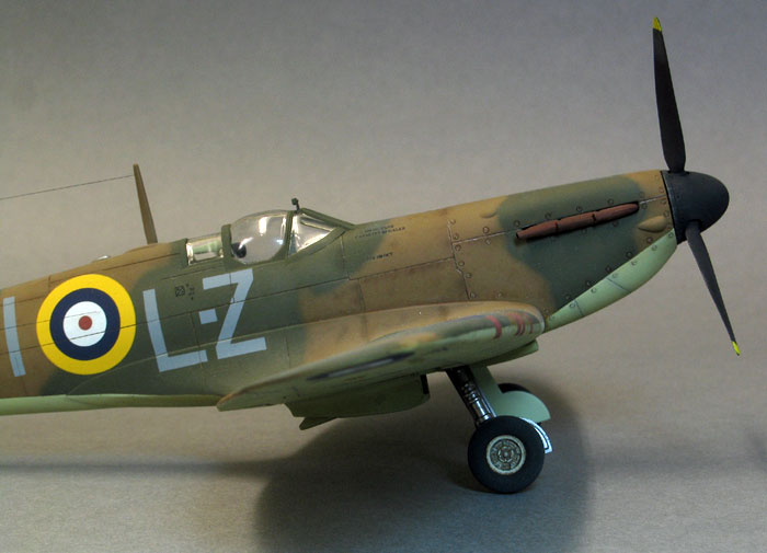
Exhausts – The kit parts would have been used but as an Ultracast spinner was already in the on-line shopping basket it was too much to resist their lovely replacements for early Spits. These are fitted to the Tamiya kit so won’t fit the Airfix kit without trimming for length and thickness. I shaved off small amounts from the length of the inserts that mount into the engine compartment until the length was ok. Only then did I carve resin off from the insert faces that will disappear invisibly inside the fuselage. Don’t carve resin from the areas outside the fuselage. Do this carefully and they’ll fit perfectly on your kit.
Radio mast – I fitted mine (pre-drilled to accept an aerial wire later) to ensure it blended in with the overall paint later. The connector over the tail / rudder is quite narrow on the real thing and scaled down lacks strength in this scale so a hole was drilled into the right location and a suitable piece of etched fret frame was cut and bent double (to give extra thickness) before being secured with CA.
Canopy – This was masked with Parafilm M and added before painting, to again ensure uniform paint. The front screen just wouldn’t snug down and needed a fair old tweaking session to bed it in. The centre section of the canopy was immediately too narrow to the point of being way off the pace, awkward as I’d already decided it was going to be buttoned up. This may have resulted from my decision to fit the spreader bar further back but if you’re opening your canopy then this clearly won’t be an issue. I just resorted to some oil paint filler mix being slathered into the shelf created by the shortfall in width, smoothed and then sprayed it with plenty of camo. This has disguised it to a great degree but ideally it still demands a vac replacement. The rear section then revealed that it was short on length as it gapped a little with the hood. I wasn’t about to pull the lot of and vac it as this model was very much a ‘just have fun’ jobbie.
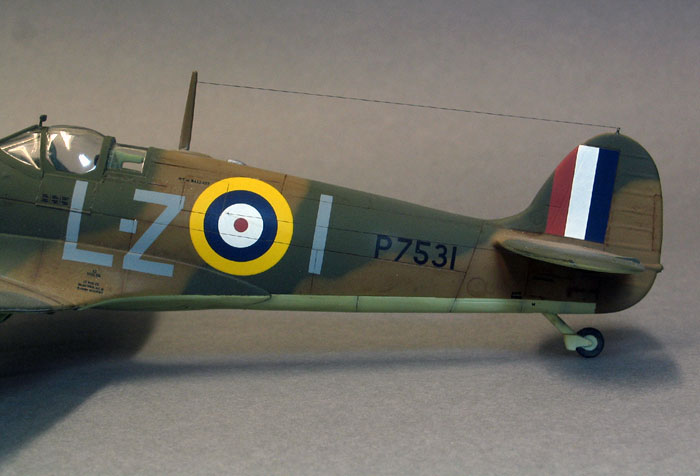
The kit decals looked ok in the box but closer inspection indicates they’ve been printed using some kind of dot matrix ‘newsprint’ method. My decal OCD kicked in at this point and the Aero Master “Battle of Britain Spitfires” 48-078 and Spitfire Basic Stencils 148-009 sheets were given a day out.
Paint began with a good hose with Halfords grey primer and after a day drying was rubbed back with 1500 Wet ‘n Dry. This really smoothed out the slightly pebbly plastic and helped the finish of the top coats later. Gunze acrylics were used throughout – Sky Type ‘S’ on the lowers, later masked for the essential sharp demarcation before the Dark Earth and Dark Green were sprayed.
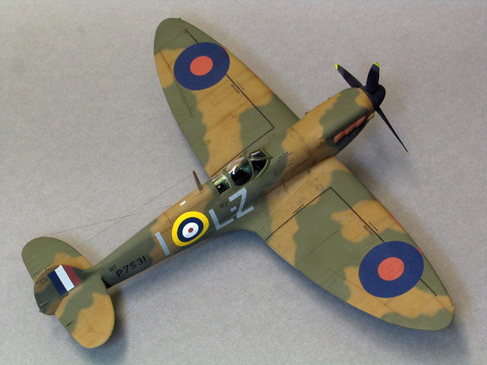
The Sky Type ‘S’ lowers were sorted and masked before switching to the upper camouflage. The Dark Earth was applied first. The areas that would be Dark Green were lightly outlined in pencil before being filled in with the airbrush at 45 degrees, pointing 'in' to the green areas at all times, to give a fairly tight feather.
The very useful weathering mix of thin Tamiya black/brown acrylic (10% paint, 90% thinners) was traced into some panel lines giving light overspray either side. Certain panel lines (mainly around the forward fuselage) had Tamiya tape run along their edges to mask one side. Horizontal lines were masked on the top side (to conform to gravity - water runs down or down and back), while vertical lines were masked along the forward edge (to conform to airflow). The thin mix was traced along the tape's edge and into the tape itself - in straight lines and sometimes 'flicking' the spray across the tape at 90 or 45 degrees into the camouflage. Now the weird part - I disengaged my conscious brain (my wife questions whether it ever gets into gear at all...so do I some times) and without thinking rapidly traced the thin spray over the Dark Earth only in a random, aimless zig-zag, up, down, side to side, all over the place non-pattern - pulling away from the surface, dodging closer - you get the idea. The key is don't think - just 'do'. Switch off the targeting computer and ‘…use The Force Luke….’ Anyway, I’d like to go back to my cell now? A light wash of oils then matt varnish and I called it done.
The decals went in with just Micro Set and Sol and a few cuts here and there with a scalpel to persuade them down between the panels. A couple of knowledgeable folks have since advised me that my Spit, being the aircraft of (the then) Flight Lieutenant Charles Green and part of 421 Flight during the Battle of Britain, should wear a PRU canopy centre section. Mine doesn’t – I regard it as a casual bit of fun in practising RAF camouflage practice before I get around to tackling my 1:32 Mk IIA.
Finishing Touches
Aerial wires were sourced from half pound breaking strain monofilament fishing line (a Japanese brand apparently reinforced with resin and ideal in this role). I deliberately fit the lines with a little slack so as not to snap the CA joints either end and tighten each with the still hot head of a match that’s been burnt about a third of its length before being blown out and placed a couple of millimetres from the aerial at various points. This tightens the line incrementally under control.
Other than the twenty-one separate areas I’ve covered the build was entirely straightforward. Yes, that was tongue in cheek but to be blunt although you can build two Tam Spits for every one of these (and most folks by now will be probably forever confirmed in avoiding this one – sadly) I sincerely enjoyed it and derive great satisfaction from seeing it become a part of my still small, miniature air force.
Newcomers to the hobby can buy one and tuck it away until a few Tam ‘slammers’ are on the shelf. It’s an ideal vehicle for getting into low level kit tweaking as well as the basics like filling with Milliput. More experienced ranch hands will walk it.
This was always going to be a mostly out of the box build, going that short hop beyond to emphasise that a couple of resin add-ons and some home spun scratching can easily help the Airfix kit more fully embody the eternal beauty of the Spitfire.
On a different note, I regularly navigate the Purley Way near to where I live, either by car or motorcycle as the need dictates. Heading south, the road ascends through playing fields, past an area that once was Croydon Aerodrome, the busiest international airport in Europe in the 1920s and 30s and later a front line fighter station when the Germans stood on the French coast and contemplated an invasion of Britain. A large RAF memorial now stands by the road in commemoration of the events and sacrifices connected with the area. I often wonder, as I motor past, one of the hundreds of thousands who do so every year, just how many are consciously aware of what the memorial and others like it actually stand for. How many hear the sound of Merlins in their mind, imagine Hurricanes bumping across the grass at full throttle and the twisting pursuits of an enemy bent on our wholesale destruction, punctuated by the rattle of .303 machine guns. A minority I suspect.
I had intended to produce a Tamiya Spitfire review for Battle of Britain Day last September but missed the boat. Nonetheless, I’d like to dedicate my Spitfire to the memory of all those RAF pilots, wherever they hailed from, who fought and died selflessly in the skys above my home. This modeller will never forget them.
References
The Supermarine Spitfire Datafile Part 1: Merlin Powered / SAM Publications (ISBN 0-9533465-2-8).
Aircraft of the Aces – The Legendary Spitfire Mk I/II 1939-41 / Osprey Aviation (ISBN 84-8372-204-6).
Steven Budd – sdkfz124wespe@yahoo.co.uk
Model, Images and
Text Copyright © 2008 by Steven Budd
Page Created 21 April, 2008
Last Updated
21 April, 2008
Back to HyperScale
Main Page |
 Home
| What's New |
Features |
Gallery |
Reviews |
Reference |
Forum |
Search
Home
| What's New |
Features |
Gallery |
Reviews |
Reference |
Forum |
Search