|
Hobby Craft's 1/48 scale
Curtiss Hawk 75 A-2
by Randy Lutz
|
|
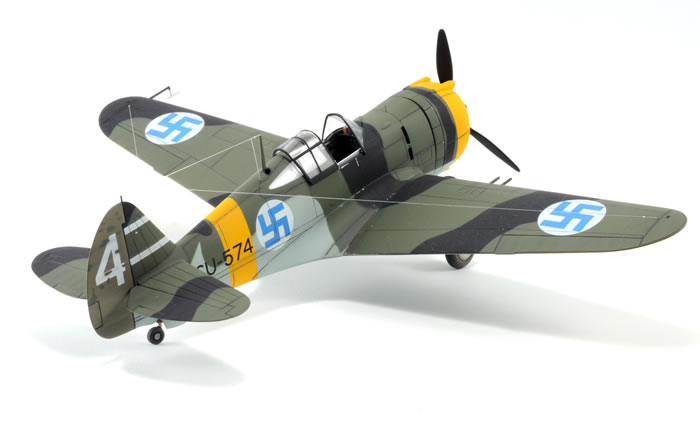
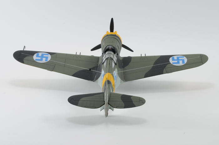
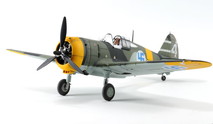
Curtiss Hawk 75 A-2 of
Havittajalentolaivue 32, Nurmoila, Russia, February 1944 |

HyperScale is proudly supported by Squadron.com
Detailing and improving the Hobby Craft 1/48 Curtiss P-36 to model a Finnish Curtiss Hawk 75 A-2 of Havittajalentolaivue 32, while based at Nurmoila, Russia during February of 1944.
This Curtiss Hawk is part of another one of my grandiose modelling plans, which never seem to come to fruition. About ten years ago I thought it would be a great idea to model a collection of Curtiss Hawks representing each nation that operated the P-36/Hawk 75. By my estimation, the P-36 was flown in the markings of the UK, South Africa, USA, Brazil, Dutch East Indies, Norway, France, Germany, Portugal, Peru, Argentina, China, Thailand, Iran and Finland. Well that's 15 countries and I have managed only one in ten years. At this rate, I will be dead before I can finish another three.
The starting point for this build was based on the Hobby Craft P-36A/C USAAC, kit HC1555, however I could just as easily have used HC1546, which is the P-36 Pearl Harbor Defender, or the Curtiss "French" Hawk 75, kit HC1560, as both of these kits have the correct engine/cowl assemblies. You are invited to refer to IPMS Canada’s Random Thoughts Volume 27, Numbers 2 and 3, or Model Aircraft Monthly Volume 3, Number 10 for a detailed breakdown of the variants of Curtiss Hawks and the particulars of the various Hobby Craft boxings.
The first step was to go through the kit and remove all the parts that would not apply to a Finnish Hawk 75 and to also determine where I would have to correct, or modify the kit to improve the accuracy. When I mention accuracy, I do not mean that I compared the kit to scale drawings to verify length and wingspan etc., as I have found over the years that you can never really be sure that the drawings you are using are accurate. Besides, I subscribe to the theory that if it looks like a Curtiss Hawk, then it must be a Curtiss Hawk and I don't need to go searching for problems. I have my job for stress and I sure don't need any stress in my hobby. If you choose to be a rivet counter and use a micrometre to make sure the tail wheel strut is the right diameter, go ahead and I hope you have a nice life.
Anyway, I digress. When it comes to Curtiss Hawks, it really helps if you have a photo of the particular machine you wish to model, as this aircraft featured so many numerous small detail differences that it is next to impossible to find any consistency. I guess in the simplest of terms the only consistency I could come up with total inconsistency. I wanted a Finnish Curtiss Hawk that was not in post-war markings, had two-tone upper surfaces and did not have the black lower wing and going through all my decals, I was left with only one option, specifically CU-574 from Aero Master 48-60 Foreign Hawks. Fortunately, I managed to locate four different photos of CU-574, taken at various stages of its career, which helped to identify some of the details of the airframe.
Like most kits, I started with the cockpit and I found that Hobby Craft has provided a reasonable looking cockpit, albeit a little basic. Before one becomes to critical of Hobby Craft's efforts, remember you get what you pay for and Hobby Craft kits tend to run at 1/3 -1/2 the price of the Tamiya and Hasegawa kits. I started by removing all the interior details from the fuselage sidewalls, as I would be using the resin sidewalls from the Hi-Tech detail set 48023 for the P-36. As a rule, I do not care for Hi-Tech's resin as I find it chalky, grainy, rough and lacking a sense of refinement. However, it was all I had and none of my local stores that pass themselves off as Hobby Shops carry any aftermarket detail sets. I then glued the fuselage halves (parts A1 and A2) together and the installed the rear cockpit bulkhead, part C25. I followed this procedure, as I wanted to make sure I had the bulkhead perfectly aligned with the upper portion of the cockpit behind the pilot's head to result in a seamless area behind the pilot.
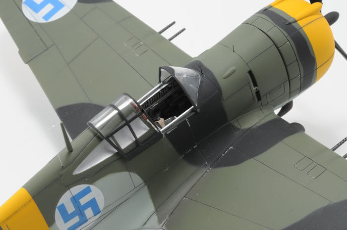
This is also an excellent time to point out a potential pitfall with the kit, as it relates to the installation of the rear quarter glass and I will tell you how to work around it. If you attempt to install parts D7 and D8 which are the clear parts behind the pilot, they will either fog up and get cloudy from the super glue or liquid cement, or if you use Kristal Kleer, you will have glue seepage on the inside of the glass. This is guaranteed 100% to happen because of the way the mating surfaces are designed. To eliminate these problems, you have to do two minor things. The first is to scribe a deep channel all around the inside edge of the window opening, for which I used a combination of a sewing needle in a pin-vice and my OLFA plastic cutter. The second thing to do is thin the inside edge of the clear parts D7 and D8 to at least half their thickness. By performing both these steps you are effectively reducing the surface contact area between the clear parts and the fuselage, while also allowing an area for any excess glue to channel away before it wicks its way up onto the glass. Once you install the clear parts, you can fill any seams and then sand and polish to restore the clarity of the windows.
Back to the cockpit sidewalls. The two parts were airbrushed with Testors Metalizer Non-buffing Aluminium, given a black wash and then smaller details were picked out using Black Chrome, brass for the fire extinguisher and leather and gunmetal for the flare pistol, while the row of flares were detailed with red, green and brass. These parts were fastened to the fuselage halves after the fuselage interior was airbrushed in Non-buffing Aluminium.
Next I tackled part C26, which is the cockpit floor, as it is devoid of any detail. Depending on which references you look at, the floor could resemble an early P-40, or it could resemble an early P-40 with what appears to be two, wide, shallow U-shaped channels for the pilot's feet, which is what I opted for. I also added strip plastic to represent the prominent joint that runs down the middle and then painted the floor Chromate Yellow and not Interior Green. The cockpit colour of the P-36 lineage is a subject that is discussed frequently on the various modelling web-sites. Without being dogmatic about it, the general consensus is that the P-36 was built before the introduction of Interior Green paint and was most likely finished in aluminium lacquer, with Chromate Yellow applied to the rudder pedals and floor, which is actually the top of the wing. This is supported by the colour photos of the unrestored cockpit of the US Air Force Museum's P-36 in Dayton, Ohio.
Moving forward, we get to the instrument panel and cowl gun decking, parts C16 and C21 respectively. I had the option of using Hi-Tech's instrument panel, but truth be told, I did not feel that Hobby Craft's was all that bad. It only needed the addition of a few knobs, which I made by punching out disks of plastic using my Waldron punch set. The cowl gun decking has what I assume are gun breeches, but as they are too narrow and are partially hidden behind the instrument panel, I fashioned new gun butts from Evergreen strip and rod styrene. The instrument panel was airbrushed with Testors Black Chrome, while the lower part with the rudder pedals was airbrushed with Testors Chromate Yellow and the gun breeches were airbrushed with Testors Gunmetal. Mike Grant instrument dials were applied to the panel and each dial was given a drop of Future floor wax to represent the lenses.
The seat was next to be enhanced. Usually, the seat is the single biggest improvement you can make to any cockpit, as for the most part it is all you really look at in the cockpit of a finished model. I had loaded up on a supply of Ultracast resin seats with both U.S. and Sutton style harnesses, but they would prove useless for this build, as my seat needed to have German style seat belts. This left me with no other option than to liberate a seat from my Hasegawa P-40E. The seat was airbrushed with Alclad Aluminium, given a dark wash and treated to set of Eduard German style photo-etched seatbelts, which I had painted off-white and dry-brushed with a medium brown.
With cockpit finally completed, I was able to get to the assembling of the basic airframe. The first thing I did was to correct the engine mount. The way Hobby Craft has designed the kit the engine will sit too deep in the cowling, resulting in the prop hitting the lip of the engine cowl. This is an easy fix that took a few minutes. I laminated two pieces of .040 styrene and one piece of .020 styrene together, drilled a hole to match the mounting boss on the back of the engine and fastened the laminated styrene to the front of the fuselage. This positions the engine further forward and allows the crankcase to protrude past the cowl lip as it should. The engine was painted with Metalizer Steel, and given an India Ink wash to highlight the fin detail on the cylinders. The crankcase was painted with Xtracolor X128 Engine Grey FS 16076, given a black wash and dry brushed with a lighter grey, while the spark plug leads were made from pieces of fine solder. Overall, I think the Hobby Craft engine looks pretty good, even if it is a little basic.
There is another problem with the engine cowl and it involves the exhaust pipe cut-outs. Hobby Craft has moulded the openings a little bit irregular in shape and with openings that are too big at the edge of the cowl. I filled the irregular shaped holes with strip styrene and then using a cutting burr in my Dremel, I enlarged the openings to the right size and shape. While dealing with the exhaust openings, this is as good a time as any to touch on the exhaust pipes themselves. The Curtiss Hawk I was modelling had the long, unshrouded exhaust pipes, which are not properly supplied by Hobby Craft. I found that a set of the long pipes from the Tamiya Rex had the right basic shape and diameter to work in this instance and all they needed was to be trimmed off to the right angle and hollowed out.
The main wing was next and if you are lucky it will be moulded with the correct dihedral. I have nine Hawk kits at home and of the nine, four have the wing moulded with absolutely no dihedral. In this case, cut a v-shaped notch into the re-inforcing rib inside the bottom, so as to allow some flexibility in raising the wingtips up a little. There are a few other things you need to do to the wings, depending on which variant of the P-36/Hawk 75 you wish to build. Hobby Craft gives you a pretty generic wing, meaning there are no gun access panels indicated on the upper surfaces, so you will need to scribe in one or two panels per wing to correspond to the number of wing guns fitted. Interestingly, Hobby Craft gives you wing gun ammo access panels on the underside which you will need to fill in based on the version you are modelling. A little bit of a disconnect there. Once you get that out of the way, you only need to decide if your Hawk should have the bomb racks Hobby Craft offers, or if they should be removed.
Once the wing is installed, you will have to use some filler at the front, along the bottom, where the wing meets the fuselage just behind the exhaust openings. This was by far the worst fitting aspect of the kit. If the wing is installed carefully, you will have no bodywork to perform along the wing roots. This is as good a time as any to add the fuel tank drain and vent pipe. The tail planes were fastened and fit quite well. However, they are missing the panel lines, so using the scale drawings in the AJ Press books, these lines were scribed in.
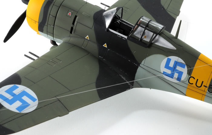
The clear parts were next and Hobby Craft has made the same mistake as all other kits in as much as they have moulded a set of vertical canopy frames on the outside of the windscreen, when in reality, these should be two pairs of metal wires on the inside. This is an easy fix and takes no more than 5 minutes with a scriber. Using the external frames as a locating guide, scribe two sets of parallel lines on the inside of the windscreen. The using a sharp pencil, run the lead in the scribed lines. After that, sand off the two frames on the outside and what you have left is the illusion of metal wires on the inside of the windscreen. You will also notice that the windscreen has been blended into the fuselage, resulting in a much neater installation. In the same photo, you can also make out he Revi gun sight, which was installed, in keeping with the German instruments and seatbelts. On the topic of the clear parts, the kit’s sliding canopy will work quite well with one simple modification. Add two thin strips of styrene to the inside edge, near the bottom, as these will keep the canopy from sitting too low if installed in the open position. It is ironic that in most models, the kit canopy will sit too high and usually needs to be replaced with a vacuform copy, but God bless Hobby Craft, they will do the exact opposite.
With the complete airframe assembled, virtually no filler putty was needed on any of the joints, aside from the previously mentioned bottom. I cannot emphasize enough the importance of test fitting any kits before committing glue to plastic. A little work up front can pay dividends in reduced body work later on in the construction. To mask the canopy, I did not use any of the readily available commercial masks offered. I have found that most canopy masks are designed to go right to the edge of the clear part in applications where there is a window which gets inserted into an opening such as the P-40B/E, Dewoitine D.520 and the P-36 and consequently do not allow for the seam to be hidden. So, I made a master set from masking tape to the exact shape I wanted and had my local trophy and engraving shop scan them and make multiple copies from vinyl. For a sum of $15.00, I got two dozen sets of masks, which I know will fit perfectly every time. Sure beats paying $6.00 for a set of two masks which will require trimming to fit.
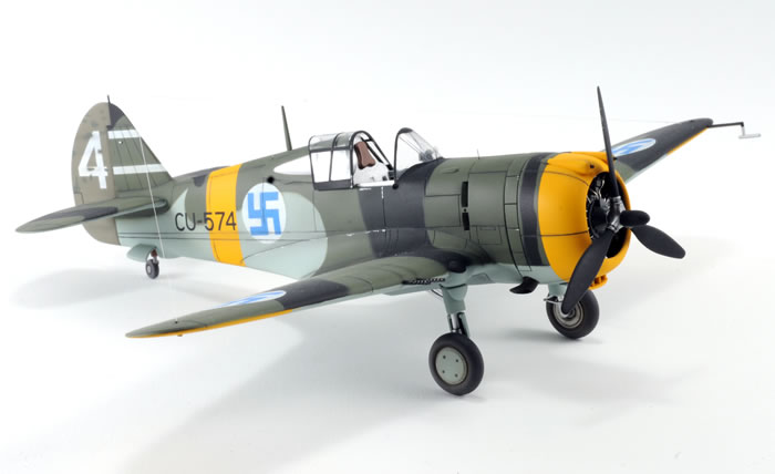
Paint
Now I was at the stage which I loath, namely painting. First, I airbrushed Xtracolor X106 Insignia Yellow FS13538 on the nose, fuselage band and underside of the wing tips. Next, X113 Faded Olive Drab was mixed with X201 RLM Grau 02 and applied to the rudder to represent the replacement rudder that was fitted to CU-574. This is a perfect example of how important photos are of the subject you are modelling. In the Aero Master instructions, they show the rudder as a different shade from the rest of the airframe, but they make no mention of this fact. They also show it having light blue on the bottom, whereas the wartime photos clearly show it with a solid darker colour all the way to the bottom. Also missing from Aero Master's artwork, are all the small patches from previous damage and repair.
 The rudder and yellow areas were masked off and then the under surfaces were airbrushed with X127 Blue FS15414. The rudder and yellow areas were masked off and then the under surfaces were airbrushed with X127 Blue FS15414.
For the upper surfaces, I used a combination of X155 B-52 Dark Green FS14096 and Testors Model Master Gloss Black.
A particular things to note is how the upper and lower camo demarcation line is different from one side to the other.
Decals
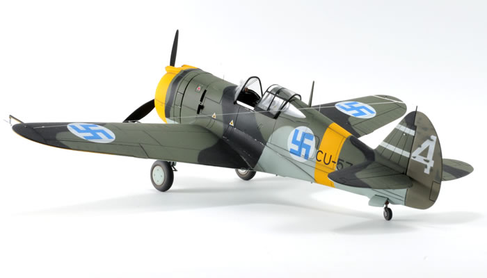
The decals were next to go on and as is the norm with the older Aero Master decals, they are printed by Micro Scale and performed flawlessly. The German style oil and fuel filler triangles were liberated from some older decals featuring Luftwaffe subjects. Once the decals were in place, I created a template of the rudder area from a paper index card, drew in the location of the white "4" and then proceeded to cut irregular shaped openings in the areas that correspond to the patches on the rudder as seen in the wartime photos. The template was held in place against the port side of the rudder and X155 Green was shot through the holes. The template was then reversed for the opposite side and the exercise repeated, as I surmised that whatever had hit the rudder stood a good chance of going all the way through the fabric and exiting on the other side. At this stage all that remained was some to install all the small bits laying around, give it a flat coat and apply some chalk pastel weathering, paint the navigation lights and add the stretched sprue antenna wires. There were many other small details that I added and numerous corrections or enhancements performed on this model, but to list them all may only serve to put you to sleep.
Usually when I build a model, whether it be major or minor, invariably something goes wrong and causes a setback. In this case, I can't recall any problems. I may have had more things to do, but nothing that wasn't anticipated in advance. The finished product now ranks as one of my most satisfying and favourite models to date. It is not a shake and bake kit (you cannot begin to imagine how I hate the use of that term, as I have seen numerous supposed shake and bake kits that once assembled, looked like polished turds). To build it means you will need to use some of your dormant modelling skills, but I can tell you that you will have a greater feeling of accomplishment with this kit than you will with a state-of-the-art Tamiya or Hasegawa.
-
Suomen Ilmavoimien Historia No. 5 Curtiss hawk 75A and P-40M, by Kalevi Keskinen, Kari Stenman and Klaus Niska
-
Suomen Ilmavoimien Historia No. 20 LeR 1, by Kalevi Keskinen and Kari Stenman
-
Suomen Ilmavoimien Historia No. 23 Sotamaalaus Warpaint, by Kalevi Keskinen and Kari Stenman
-
Wydawnictwo Militaria No. 103 Curtiss 75 Hawk, by Seweryn Fleischer
-
Random Thoughts 27-2, IPMS Canada
-
Random Thoughts 27-3, IPMS Canada
-
Mallari, No. 3, July 1972, IPMS Finland
-
AJ Press Monograph No. 61, Curtiss P-36 Hawk Part 1, by Marek Rys
-
AJ Press Monograph No. 62, Curtiss P-36 Hawk Part 2, by Marek Rys and Seweryn Fleischer
-
AJ Press Monograph No. 63, Curtiss P-36 Hawk Part 3, by Jiri Chodil and Seweryn Fleischer
-
Historical Aviation Drawings No. 7-62-A, by Paul Matt
-
Detail and Scale Volume 61, P-40 Warhawk Part 1, by Bert Kinzey
Model, Images and Text Copyright ©
2009 by Randy Lutz
Page Created 5 January, 2010
Last Updated
25 January, 2010
Back to
HyperScale Main Page

|
 Home
| What's New |
Features |
Gallery |
Reviews |
Reference |
Forum |
Search
Home
| What's New |
Features |
Gallery |
Reviews |
Reference |
Forum |
Search