|
Encore's 1/32 scale
Fokker Dr.I (521/17)
by Bruce Salmon
|
|
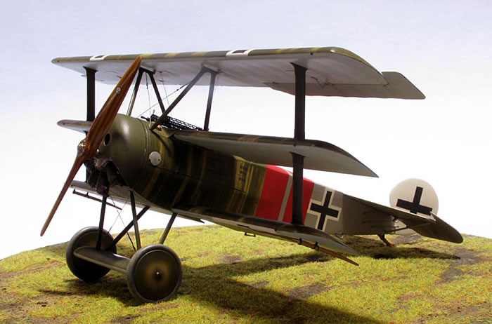
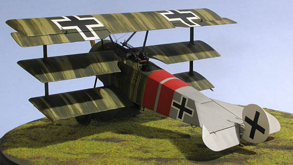
Fokker Dr.I (521/17)
Roden (Encore) 1/32 Oblt. Robert Greim – Jasta 34b 1918 |

Encore's 1/32 scale Fokker Dr.I is available online from Squadron
The kit I used for this project was the Encore Models Fokker F.I Dreidecker 'Voss'. This is basically a reboxing of the Roden kit but with a PE set, resin engine, corrected rudder etc, Cartograf decals and a groovy 'Voss' pilot figure.
Conversion to a Dr.I is easy as all the parts you need are in the box... Straight edged tail plane, wingtip skids, cowl without lower flange, short width aileron counterbalance tips.
I bought the kit on sale from Squadron and it arrived on New Year's Eve. The cost of postage was nothing short of daylight robbery - basically three times the cost of the same size kit from Hannants (in the UK) which is much further from New Zealand than the USA.
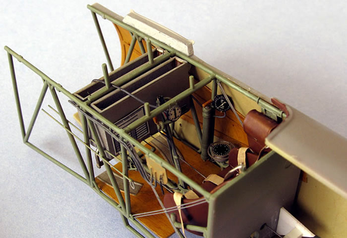
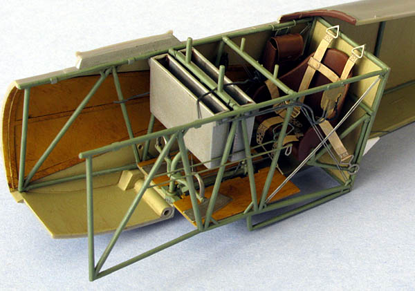
Interior
I started out by building and painting all the interior subassemblies so that I could dry-fit them and check for any potential problems. The completed cockpit floor was glued to the right side framework and the seat / fabric bulkhead assembly. As the glue was drying I dry fitted this assembly to the right fuselage half to make sure everything was in alignment. Once the glue had set I rigged the control cables. Next I glued on the left side framework and then dry fitted this whole assembly within both fuselage halves to make sure it was all good. Finally I glued it permanently to the right fuselage half.
Now this is where the instructions turn to custard... Part 16C attaches between the first two knobby bits forward of the seat position and then the upright handle bars (part 22C, arising from the cockpit floor) attach between the second two knobby bits. The ammo containers (parts 4D) attach from the underside of the framework very slightly (1/2mm) fore and aft of part 22C).
Next I ensured that the tail skid would fit properly then glued the two fuselage halves together. Once dry I bogged and sanded the seam lines then drilled holes for the lifting handles which were replaced with brass wire so I couldn't break them off.
Now I attached the fuel tank to the underside of the middle wing / forward fuselage deck assembly using some bits of plastic strip for support. This ensures that the fuel tank filler pipe will line up precisely with the hole in the forward fuselage deck. Make sure you dry fit this assembly to the fuselage while the glue is drying so you can make any necessary adjustments.
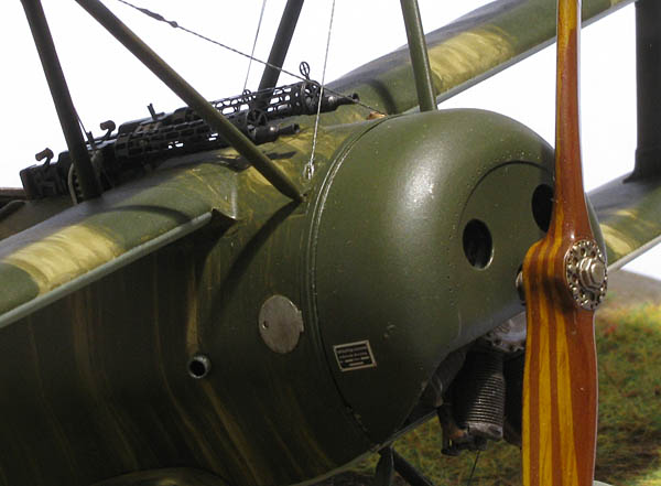
I also added two engine inspection hatches on either side of the fuselage just aft of the cowl which were gleaned from a Tom's Modelworks Albatross D.III PE set. After having finished the model I found that they should be much bigger circular plates.
MGs
The MGs go together easily and the PE looks very good. Be very careful that you make them exactly the same or they will look uneven when they are finally positioned in such close proximity to each other. If you use the PE guns then fill the holes in the upper deck where the solid plastic ones would attach. You might also want to round the middle of the gun padding (part 6C) as the padding covered a metal tube on the real thing. Now make sure your MG assembly fits into the gap in the forward fuselage deck with enough clearance to wiggle it slightly so that the MGs can point straight ahead and not off to one side. I painted mine with Humbrol Metal Cote 27004 Gun Metal then buffed it with a fuzzy brush. Leave the MGs off until later in the build so you don't break them.
Engine
The resin engine is a gem and required very little effort to prepare. I attached each pot with half-set (syrupy) superglue so that I had the time to ensure they were aligned before the glue set. You need to sand down part 8E so that it will attach properly to the back of the engine (I used the plastic engine as a guide). Getting it to sit central was a mission - if you don't your engine will be wobbly when it rotates.
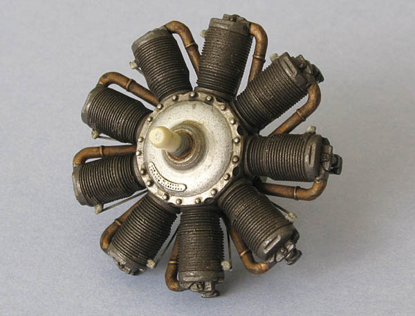
Once completed I sprayed it aluminium and hand painted the carburettor pipes brass. I then picked out the wiring etc with a fine paintbrush and finished up with the magic of several dirty washes using oil paints.
Wings
Now I attached the middle wings to the fuselage and the painted firewall to the front end. I also glued the tailplane on at the same time to make sure that it would be level with the wings. Once everything had set I dry fitted the wing interplane struts and then painted them, the wings , axle fairing, fuselage, rudder, and most of the other bits.
I first found this aircraft's colour scheme worn by a replica Dr.I in a book titled 'On The Wings of History' which is about the beginnings of The Vintage Aviator collection here in New Zealand. It can also be found in the Windsock Datafile Special on the Dr.I.
After priming the whole model I painted the top sides of the wings with a doped linen colour then applied the green streaking using a round brush and paint thinned to varying degrees. Starting out with normally thinned paint for the darkest patches, waiting for that to dry for an hour then and even more thinned mix, waiting another hour then an even thinner mix and so on - very time consuming. Once I was happy with the effect I masked and sprayed the underside blue then post-shaded using that colour lightened slightly with white - the Xtracolor paint took 4 days to dry - GAD!
On the fuselage I masked and sprayed the red stripes and then the silver doped fabric. Next I set up to mask the crosses. It was now that I discovered the fuselage cross wouldn't fit where it was supposed to... on further investigation I found that I had followed the replica aircraft's scheme which is wrong so I had to mask the stripes all over again following the Windsock wartime photo. It gets worse... I was too lazy to sand off the paint ridges between the two colours the second time round so when I had finished painting and unmasking I reluctantly realized that I was going to have to fix the mess - third time's the charm as they say. Later I made more masking mistakes following the same 'slack bugger' pattern. All in all it set the build back by about two weeks.
The only decals used on this model are the Axial trademark on the prop, the name plate on the right side of the cowl and the weight stencil on the left side just forward of the cockpit. The weight stencil decal isn't provided with the Encore kit so I had to source it from the Hyperscale forum (Thanks to Richard from Challenger N Scale who supplied me with a spare Roden sheet). This decal went on well without any silvering but dried to a horrible orange peel effect. Thankfully it was disguised with several coats of matt varnish.
Paints used are as follows (all enamels):
Inside:
Doped Fabric: 8 - Tamiya XF55 Deck Tan / 2 - Humbrol 74 Linen
Plywood Side Panels: 5 - XF59 Desert Yellow / 2 - XF2 Flat White (drybrushed with oils then oversprayed with clear yellow/orange 50/50)
Internal Framework:
Pale Greenish Grey: 1 - Tamiya XF65 Field Grey / 4 - Tamiya XF2 Flat White
Silver Doped Fabric: 2 - Tamiya XF16 Flat Aluminium / 1 Humbrol 64 Light Gray
Topsides:
Doped Fabric: 8 - Tamiya XF55 Deck Tan / 2 - Humbrol 74 Linen
German WWI Green: Tamiya XF62 Olive Drab
Undersides:
Light Blue: Xtracolor X243 German WWI Blue
Weathering
After a coat of Estapol gloss varnish the model was given an overall wash with a 50/50 mix of Windsor & Newton Artisan water mixable raw umber and burnt sienna oil paint mixed in Bars Bugs car window washer detergent. Oil stains were then made by further darkening the original wash with black. Some restrained chipping using Tamiya XF16 Flat Aluminium was also applied to the metal parts with a fine brush. Finally I sprayed a coat of satin varnish to finish the job.
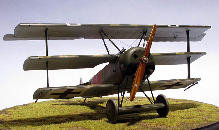
Wing Fit
Now it was time to do a trial fit of the bottom wing to see what nightmares lay in wait. I soon discovered that the wing interplane struts were too short! Essentially the middle wing strut 'fairings' (both upper and lower) disappear below both surfaces of the wing (perhaps this middle wing is too thick). Not only that but also the lower wings have to be bent upwards to ensure the lower strut 'fairings' sit deep enough into their upper surface (the lower wings are supposed to be straight). I just split the difference on the middle wings and will have to live with bent lower wings.
I then attached the MGs before the top wings were glued. You will need to cut down their cockpit framework mounting pins as they are a bit too tall.
Next I rigged all the aileron control cables in the top wing and the bracing wires in the forward fuselage upper deck. The top wing was then dry fitted onto the wing struts and the cabane struts were held in position to make sure they would look even. Then I ran some liquid cement around the wing/strut join and waited for it to dry. Next I superglued on the cabane struts and attached the bracing wires. Once this was completed the top wing is pretty secure and won't move - you can certainly feel the weight of it! The aileron control cables were then glued into their respective holes in the upper deck but were not tightened until the end of the build to prevent any sagging due to handling. Make sure your model is sitting upright on a flat surface when you rig it. If you turn it upside down or sideways the shifting weight of the heavy top wing will cause the wires to sag. Note: The bracing wires were made using a woven nylon cord and the control cables were stretched sprue.
Undercarriage
Attaching the undercarriage was a near disaster and took most of a day to complete. Firstly I trial fitted it and found that one side sat higher than the other so I trimmed the struts slightly. Satisfied, I now anchored the rigging wire ends then glued it to the fuselage using semi-set (syrupy) superglue so that I would have time to adjust the undercarriage before it set. During this process I found that the 'too long' struts weren't too long at all so had to whip it off quickly and trim the other side a bit. Happy that it was now level I left it to dry. Upon returning I found that I had forgotten to make sure it was even fore and aft so I had to cut off the forward struts at the fuselage join and reposition them. I hope that superglue holds!
I cut out the tyre valve access holes on the inner wheel covers and made spokes inside using short lengths of wire. I also flattened the tyres a bit. Once painted I attached the tail skid to the fuselage first and then glued the wheels on so that I could turn the flattened areas to sit flat on the ground - then I tightened up the rigging. After painting the wires I found that one of them now sags a bit. I guess that's to be expected as they have to support a lot of weight. Using some sort of elastic for rigging would eliminate the sagging but unfortunately you would not get the strength that you require for the structure.
The wheels also bowed upwards markedly as there was no plastic near the edge of the axle fairing to glue them to. Later I crammed in loads of superglue through the narrow gap to sure it up.
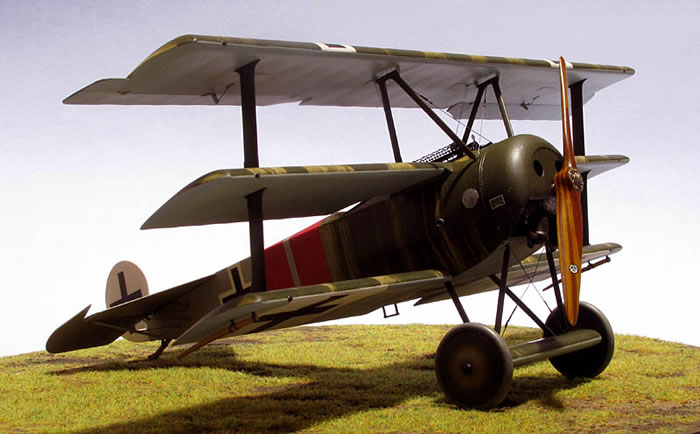
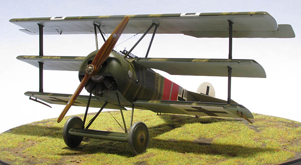
Propeller
First the propeller was primed then painted Tamiya XF57 Buff. I allowed it to dry for a couple of hours then masked it using very thin strips of Tamiya tape to represent the laminations. I sprayed the dark wood colour using 50/50 Tamiya XF59 Desert Yellow and Humbrol 133 Satin Brown. Then I damp-brushed a grain effect down the length of the blades with a 50/50 mix of Windsor and Newton raw umber and burnt sienna oil paint and also straight raw umber on the darker paint laminations. Lastly I sprayed the propeller with numerous light coats of a 50/50 mix of Tamiya X26 Clear Orange and X24 Clear Yellow.
The orange tint tends to make the dark wood 'muddy' and the light colours too orange - I am still searching for a combination to achieve the best wood grain effect.
Final Assembly
Last to go on were the delicate bits - rudder, cockpit step, tailplane braces, wingtip skids and then finally tighten those aileron cables. I also added the wing leading edge stacking pads using a drop of white glue which was then painted black.
Once complete, this is a very cool looking aeroplane. Most of the kit parts fit together very well although there are a few annoying problems. The worst problem I encountered was the wing interplane struts which were just too short... and that sagging wire (my fault in this case I suppose) may have to be fixed someday. Other let-downs are dodgy instructions for both the kit and PE and the rigging diagram is practically useless. You will need references here!
Some things I learned from this build included:
-
Shrinking stretched sprue is a one shot wonder. If you accidentally put your finger on it and sag it again there won't be enough shrink left in the sprue to tighten it up again (especially true for short lengths).
-
If the sprue is a bit too thick then it won't bend around sharp corners and needs a lot more heat to shrink it.
-
Trying to take the lazy way out will only lead to more problems.
-
Weathering and a matt coat of varnish will hide many things that go 'pear-shaped'.
-
I will probably forget these lessons and get to re-experience them during the next modelling disaster.
Now back to basking in the glory that is Wingnuts…
Model and Text Copyright ©
2011 by Bruce Salmon
Page Created 20 April, 2011
Last Updated
22 April, 2011
Back to
HyperScale Main Page

|
 Home
| What's New |
Features |
Gallery |
Reviews |
Reference |
Forum |
Search
Home
| What's New |
Features |
Gallery |
Reviews |
Reference |
Forum |
Search