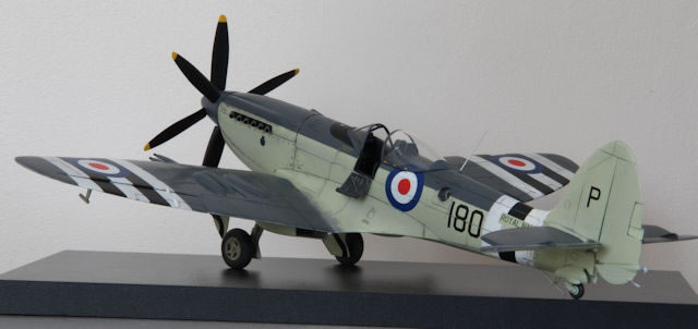
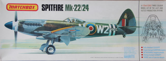
Matchbox / Revell 1/32 scale
Seafire FR.47 Conversion
by Ken Stanton

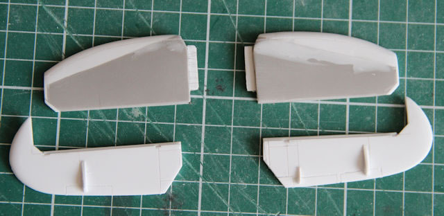
Many moons ago, I was ‘employed’ by Roomes Stores of Upminster to build kits for their window display. One of those kits was the Matchbox 1/32nd Scale Spitfire Mk 22/24.
I recall that, at the time, is was ‘fiddly’ to get the wing / fuselage alignment neat and tidy. Anyway, this was in 1978. My ‘payment’ for these builds was the return of the completed model when the window display was updated, plus an identical unmade kit. These builds, in line with the UK’s Trades Description Act, were purely ‘Out of the Box’. The only scope for enhancement was in the painting. Hence, I have had a 1978 vintage Matchbox kit that has sat in my stash ever since.
Back in 2013, Freightdog models produced a set of parts to convert this Matchbox kit to a Seafire FR47. I bought one with every intention of getting to grips with this, then, 35-year-old kit. But, like many things, other priorities got in the way.
I did, though, purchase from Hannants a Master Caster cockpit set, a Yahu instrument panel, Scale Aircraft Conversions undercarriage (Mk Vb type), Eduard Seatbelts and Master Cannon Barrels. Somewhat later, I spotted the Iconicair Griffon Spitfire cowlings and obtained those for the project also.
With the prospect of several weeks confined to barracks due to the Covid-19 pandemic, I thought this would fit the bill nicely.
I’m hoping that, even though this Freightdog conversion is no longer available, some of the challenges I encountered and the solutions I used may prove useful to others.
The first job was to re-scribe the wings and fuselage in line with drawings in SAM Publications Modellers’ Datafile #5 Griffon Powered Spitfire. I scanned the drawings and enlarged them until the drawing wingspan matched the true wingspan at 1/32nd scale. The distance from the cockpit door to the rudder post scaled at 160mm as did the kit.
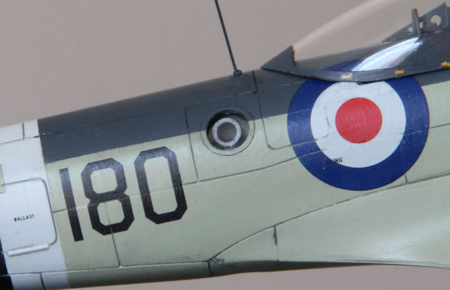
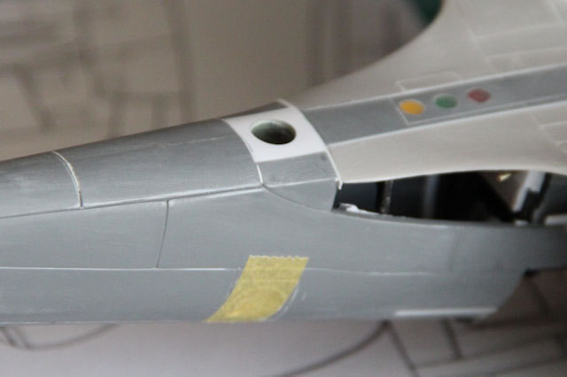
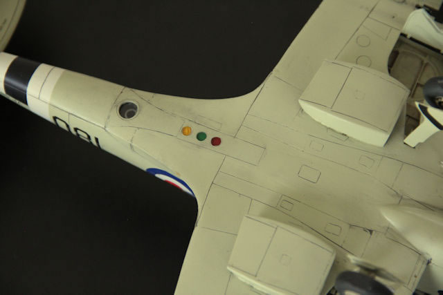
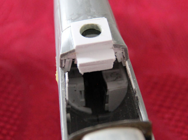
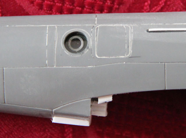
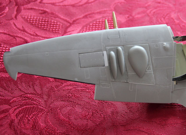
The 7mm diameter oblique camera ports were straightforward to create with care, and not taking too big a ‘bite’ between drill sizes. The final finish to these was some ‘wet and dry’ abrasive sheet wrapped around a drill shank. The vertical camera port was more challenging as it was (1) on the centreline join of the fuselage and (2) close to the aft joint with the lower wing.
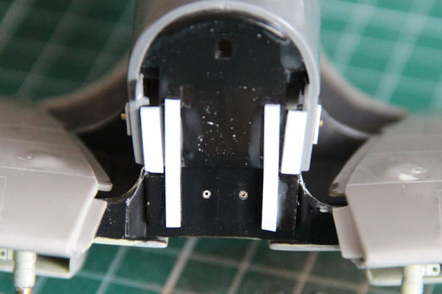
I chose to make an insert that would slot into the lower fuselage after the fuselage halves were joined. I cut out a rectangular section from each fuselage half and constructed a ‘shelf’ inside both for the insert to slide into. I made the shelf quite robust as I felt it would need to take some strain at a later stage.
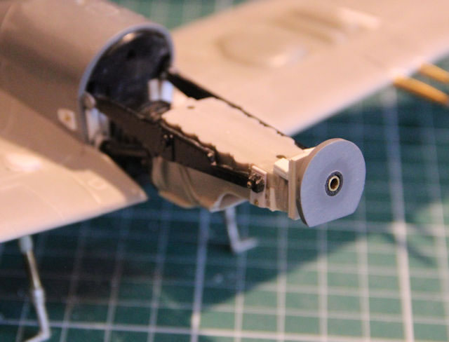
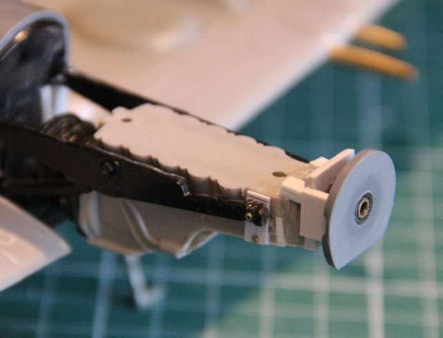
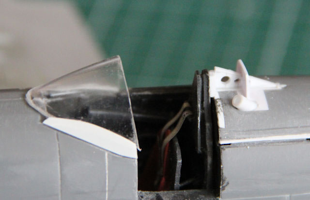
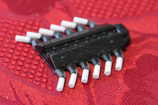
I built two identical boxes to serve as camera mounts for the oblique units and another which would eventually be mounted on the underside insert. I made a square rebate for each camera box to sit in and to trap a section of clear plastic cut from a commercial ‘bubble pack’.

I then moved on to the Master Caster replacement cockpit. The instructions gave no indication of any preparation for the kit parts so I just removed the moulded details from the area where the resin parts would be inserted. It was during the assembly of the resin parts when I realised that, although it is said to be for this Matchbox / Revell kit, the completed assembly is nearly 4mm narrower than the kit’s cockpit opening!

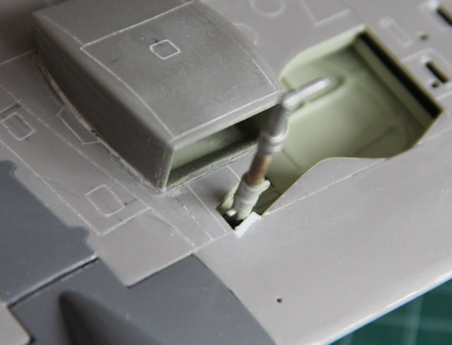
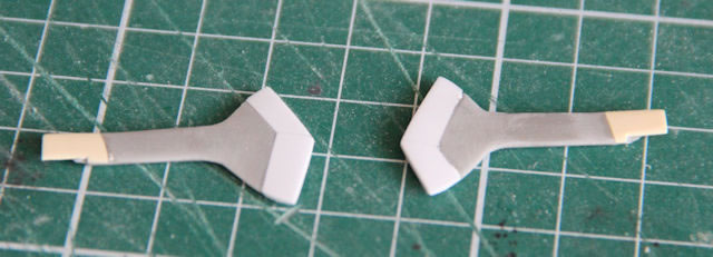
The Matchbox undercarriage legs are, to say the least, a bit basic. So, I elected to modify the Scale Aircraft Conversion ones.
I decided to attach the undercarriage legs to the upper surface of the wings prior to assembling the upper and lower wings. This was to have good access to the area where all the gluing would be done. However, it meant that there was lots of test fitting to ensure alignment was correct!
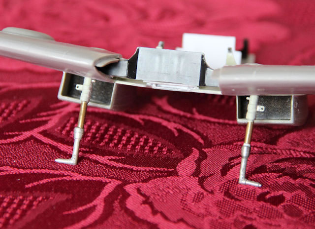
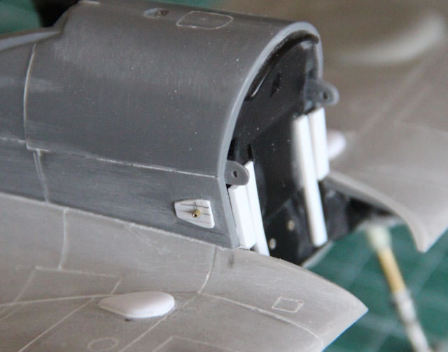
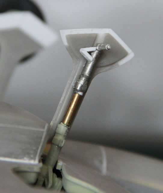
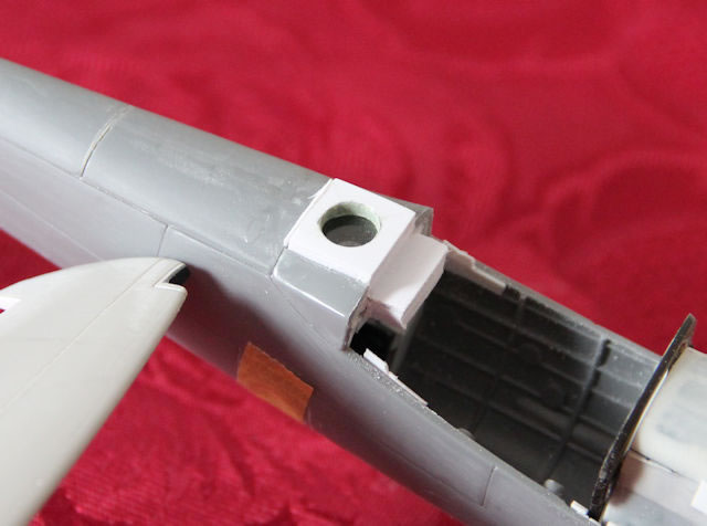
I don’t know if it was a packing issue, but the SAC pack had two identical legs. Either that, or somebody hadn’t realised that these are ‘handed’. The pivoting pintle is larger at one end. However, in the end, it did not matter as the top of the legs were eventually ‘buried’ in a structure made to fix them to the upper wing. A section of each undercarriage leg was removed and replaced with a longer piece of brass tube to get the length correct for the Seafire. I used cyanoacrylate glue to attach short sections of styrene tube over the forward pintle stubs and constructed a cradle with semi-circular cutouts for these tubes to sit in. Small circles of styrene were ‘super glued’ to the aft end of each pintle. This meant that liquid sytrene cement could be used to fix the legs to the sides of the box and to the cradles in the wing. The top of each leg was drilled to take 0.9mm diameter brass tube sections that would pass through the top of each wing to maintain the correct angle of the leg and add more support. The required areas of the upper wings were removed to accept Freightdog’s resin wheel bay and cannon breech covers.
Freightdog’s resin parts were a joy to fit. Creating apertures for the wing radiators was a bit tricky but it all went together well. I used styrene strips to reinforce the inside of the wing across the radiator ramps to give them some extra support. This meant a small part of the wing spar had to be removed to clear these so I added a plate to the spar face to restore some of its rigidity.
I took a lot of time assembling the lower wing and the spars. After removing the front of the kit’s centre section, as per Freightdog’s instructions, the spars were glued and clamped section by section allowing overnight drying before going on to the next stage. This resulted in a well aligned lower wing assembly in terms of dihedral.
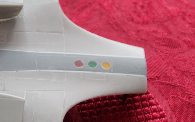
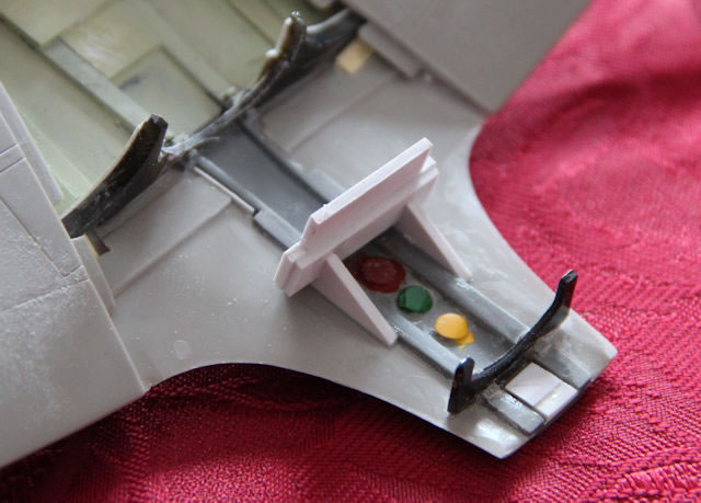
The underside identification lamps were made from clear sprue sections inserted into the lower wing centre section. These were sanded flush and polished.

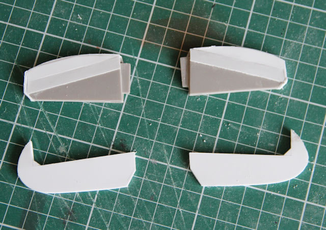
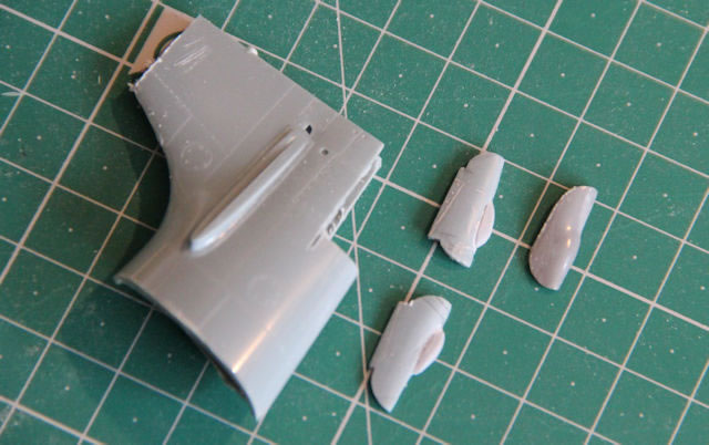
The shape of the undercarriage door opening in the lower wing is not correct for the Seafire so that was corrected. This meant that the Freightdog doors were also not quite right (designed to fit the existing kit openings) so they were lengthened and corrected. The resin doors were tricky to separate from their casting blocks and the outer skin at the base of both doors was lost. The doors were filed back, and new skins were laminated on and shaped.
Frequent taping together of upper and lower wings to check angles and lengths was interspersed with sessions of filing of the undercarriage support boxes in the wing. At that point the undercarriage legs were attached to the upper wings and allowed to set. Short bulkheads were glued in behind the cannon positions to provide support for the Master barrels. After the upper and lower wing units were glued together there was only 1mm difference in wing-tip height when standing on the undercarriage legs! Happy days!
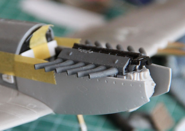
The wing leading edge was drilled out to take Master’s 20mm Cannon units. This was highly delicate and stressful. Things got very thin in places. Once each one was drilled a second drill was left in the hole to check alignment when drilling the adjacent hole.
The radiator covers were then fixed in place.
Freightdog’s upper wing panels were attached, and they transformed the look of the wing. From the plans, the ammunition compartment cover on the Seafire is shorter than the Mk 24 Spitfire (to allow for the wing folding mechanism?) so the kit part was modified and a section of styrene inserted and scribed for the wing fold join.
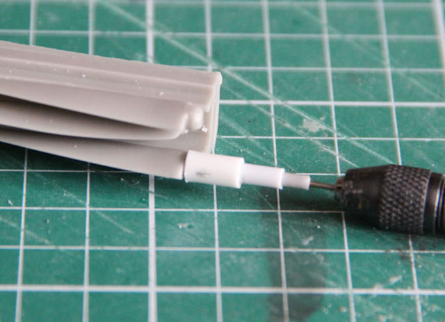
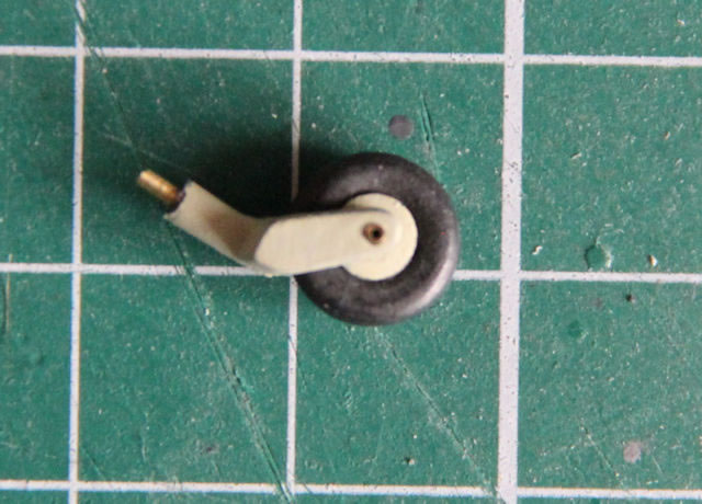
The kit’s tailwheel is a bit naff too (why do these amazing people who manufacture replacement wheels for us often neglect to include a tailwheel!). I used my Dremel to remove the hub and enlarged the hole with a drill to suit the diameter of Evergreen styrene tubing. I reshaped the tyre, as the original is flat on one side! Using Evergreen tubing I used smaller diameters to sleeve it down to a size suitable for 1 mm brass tube as an axle and created a new hub.
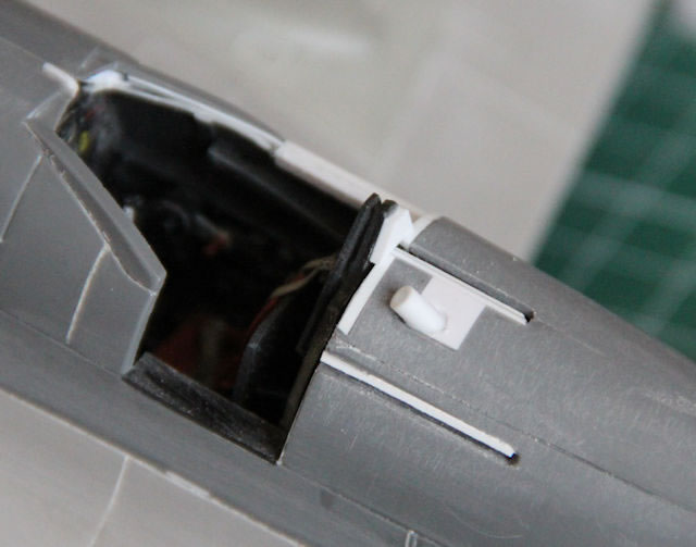
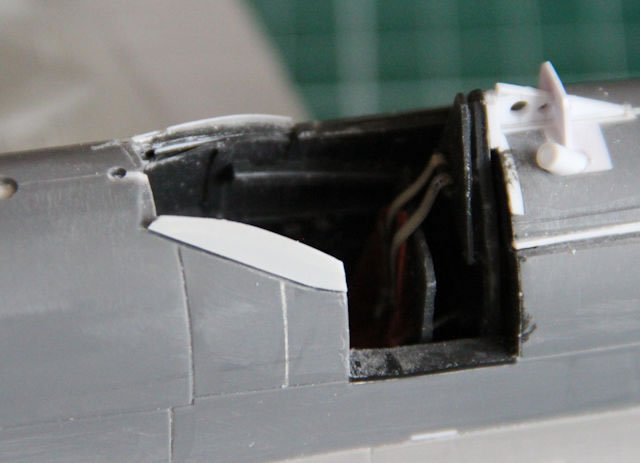
Now I had to find a way of fitting the Master Caster cockpit into the fuselage. The cockpit looked nice when assembled and painted; and the addition of the Yahu instrument panel and Eduard seat straps was the icing on the cake; but how to deal with a 2mm gap on each side and all around its rear bulkhead?
Before I tackled that, I removed the kit’s roll-over guard as it is far too thick. I also removed the section that has a ‘D’ shaped opening for the fuel filler and filled it in with a solid piece of styrene.
The best option I could see was to utilise the kit’s rear bulkhead (minus the headrest) by setting it back in the fuselage by 1.5mm and then attaching the cockpit assembly to that.
Now I was able to close up the fuselage with the oblique ‘camera boxes’ installed and the kit bulkheads in place. I beefed up the forward one (firewall) as I planned something ‘structural’ later and I was concerned it may not be strong enough.
The cockpit assembly was offered up to the kit bulkhead to centralise it as best as possible and super glue applied to the gap between it and the kit bulkhead.
As the cockpit rail grooves were very wide, I removed that section from the starboard side. Fixing a new section for the lower part of the rail also created an opportunity to cover the gap to the cockpit assembly. A similar piece was fitted into the door opening to cover the gap on the other side. With everything painted dark grey (Humbrol 66) the poor fit is not so obvious. Still not good though.
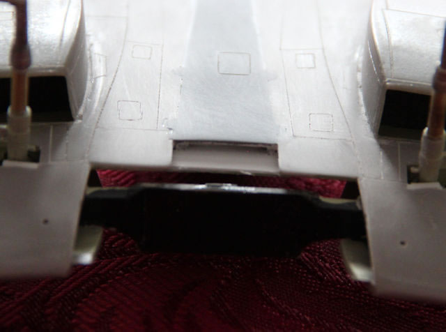
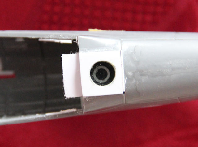
The vertical camera port insert was made from several pieces of 1.5mm thick styrene sheet glued together. Those that would protrude through the lower fuselage were 12mm square. Two pieces 12 x 18mm formed a ledge that the wing centre section would rest upon and to engage on the ‘rails’ inside the rear fuselage. Again, this was made thick enough to resist some load if filing and clamping was necessary. Once dry, I drilled a 7mm diameter hole through it and made another rebate for the camera box to sit in and to trap another section of clear plastic cut from a commercial ‘bubble pack’. This sub-assembly was then slid into position on the fuselage ‘shelf’ and glued in place to set overnight.
Now I had to face an issue that I had noticed when trial fitting the wing assembly to the fuselage. There was a distinct fore and aft curve to the underside of the wing centre section. This is where having the kit rear bulkhead fitted would come in useful. If the wing was flexed until it touched the rear bulkhead the underside looked OK (which I recall was the case 40 odd years previously!).
I constructed another, smaller, bulkhead to fit on the lower wing and positioned to abut against the kit bulkhead and let this set overnight.
Once this had set, I taped the rear of the assembled wing into position and drilled through the engine firewall into the forward wing spar and pinned them together with brass tube pins. This positively located the front and rear of the wing centre section. I then applied upward pressure to the centre section until it touched the lower part of the rear bulkhead. I drilled through my ‘bulkhead’ into the kit’s rear cockpit bulkhead and pinned them together with brass tube pins. The wing centre section now had a good ‘line’ from front to rear and the load due to the lower wing being flexed into place was taken by the brass pins. Liquid cement was generously applied to all the mating faces and left to set.
I then spent a good deal of time sanding and filing the protruding block of styrene around the vertical camera port to blend everything in. The result was well worth the effort.
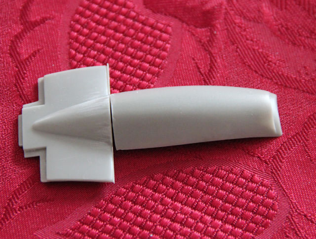
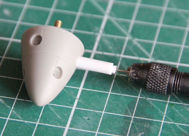
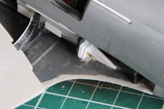
The ‘T’ section of the Freightdog air intake had been drilled and pinned to aid alignment with the nose section this was now pushed into position and fixed with CA.
Next came the job of fitting the wing fillets!
I had already assessed the fit of these to the upper wings and to the fuselage sides and they seemed good.
I had attached some small pieces of plastic card tabs to the inside of the fuselage to stop the fillet dropping below the fuselage side surface. The wing already has these moulded in.
The one thing I remembered from the first one I had made in 1978 was that there was only one way (with no second chance) to assemble these. (1) Push the fuselage join into place and then (2), using your thumbs on the curve of the fillet, slide the fillet along the top of the wing towards the fuselage until it snaps into place! Once it is in – it is IN! Liquid cement finalised the operation.
The fit wasn’t too bad. There was some sanding and filing to do on the wing joints to make them flush and the same with the fuselage where the fillet was proud of the surface. The misshapen wing bulge close to the join was removed. Some re-scribing was required. As I have done in the past, I cut away the wing tip lights and replaced them with sections of clear sprue glued in position and then shaped with sanding pads. I noted that John Miller has a ‘how to’ article recently on HyperScale demonstrating this process. Well worth a look.
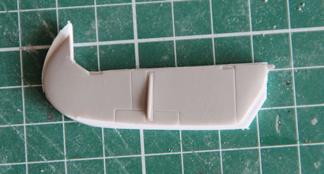
The tail-plane and elevators are one of the weaknesses of this kit. The chord is too short. As I had plenty of time to devote to this project, I decided to reshape the kit tail-planes and make new elevators from plastic card.

Every day is a school day where model making is concerned. I had cut off the leading edge of the tail-planes and inserted a section of plastic card shaped the correct profile. I then laminated progressively thinner sheets of plastic using cyanoacrylate glue to build up the thickness. A quick solution, so I thought. However, once I started to remove material to get the correct aerofoil section the law of unintended consequences reared its head. Capillary action had not carried the super thin glue all the way through the joints. So, occasionally, sections of the laminates would lift and peel away. Much reapplication of glue was required and more sanding than planned! I will use solvent in future and take my time. The elevators were made from styrene sheet.
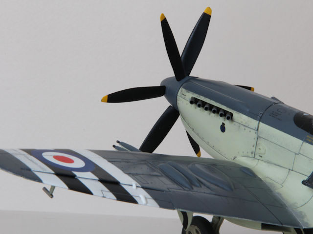
Efforts now transferred to the forward end of the airframe. The Iconicair engine panels look fantastic and fitted to the fuselage beautifully. I had to find a method to get the propeller mounting plate into the correct place.
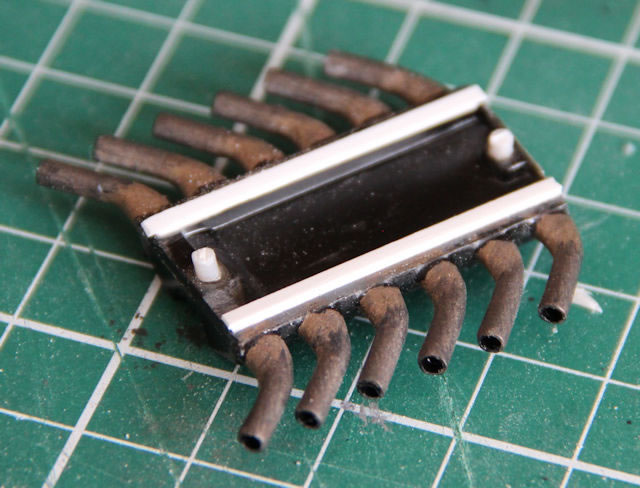
The exhausts are a bit iffy and oval in section. I cut each one off at the bend and drilled the stubs to take a plastic rod and 2.4mm o/d tube sections were glued in place. This made for a better appearance.
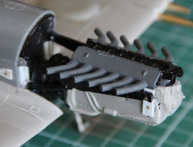
I decided at this point to use the Iconicair engine side panels as my reference/datum points.
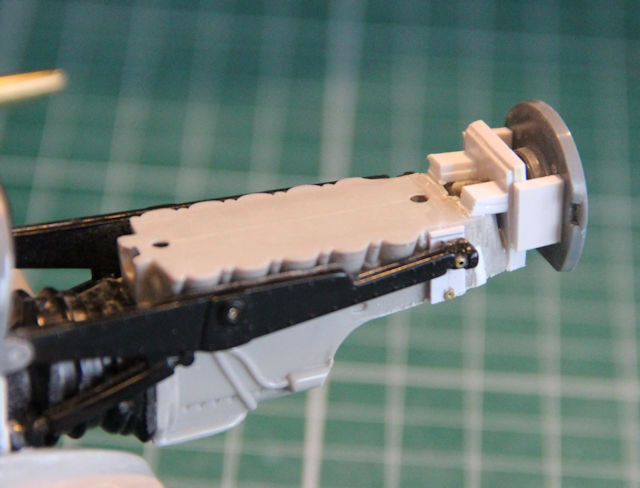
The engine block, the supercharger unit and engine bearers are necessary to position the exhausts correctly. There are holes in the sides of the engine block and there are mounting tabs on the fuselage. Now, I do not know what went wrong but there was no way that these would fit together with the exhaust stacks lined up with the apertures in the engine panels.
I suspect that, in my efforts to beef up some of the components, I had rendered inaccessible the locating holes for the lower aft mounts of the engine bearers!
The result was that I had to move the engine block down by 5mm to have any chance of getting the exhausts in the right place. I removed some material from the rear of the engine supercharger to allow the engine to rotate around the forward mounting point.
The lower aft engine mount pins were removed and replaced with long 1mm diameter pins. Holes were drilled in the firewall for these pins.
I was now able to use spacers on the lower aft mounts to raise or lower the engine block and spacers behind the supercharger to control the rotation of the engine about the forward mounts. The Iconicair panels were taped into place and a lengthy process of playing with spacers ensued to get the exhaust stubs to lay along the top of the panels. The upper firewall fixings had a habit of falling out, so a ‘T’ shaped spreader was taped in place to prevent this.
Once all this flexible construction was aligned, and gently held with one hand, cyanoacrylate glue was applied to each ‘joint’ to secure everything in place.
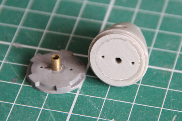
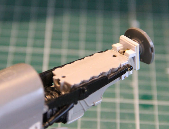
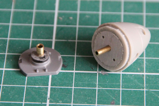
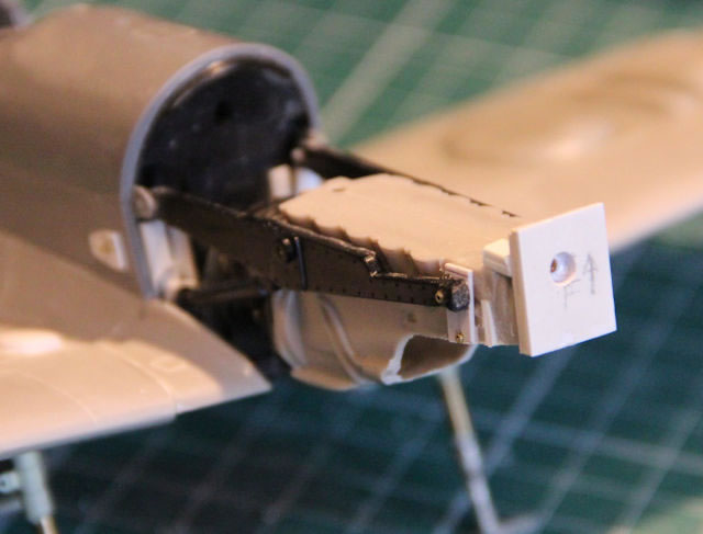
The Iconicair panels fitted very well around the kit’s propeller mounting plate. There was now the task of positioning and aligning the propeller mounting plate with the engine cover panels. I attached the kit’s propeller centre pin into the mounting plate and, after the glue had set, drilled it to take a 2.4 mm i/d brass tube which would act as the locating bush for the propeller. The Freightdog propeller hub was also drilled to take a 2.4 mm o/d section of brass tube. The plan was to get the propeller mounting plate connected to the front of the engine block and to align it with the forward edges of the engine cover panels.
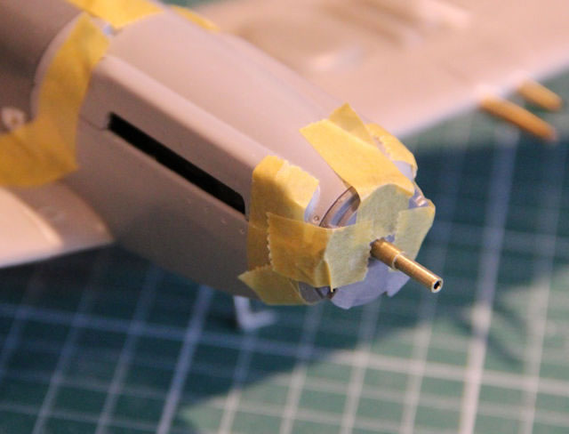
Measurements were taken and a spacer was made from plastic card with a hole drilled through to allow a 2.4 mm o/d brass tube to pass through. The Freightdog conversion has the contra-rotating propeller included, so all the Matchbox propeller parts were redundant. I drilled and bushed the kit’s propeller back plate, reversed it, and used it as an alignment jig for the panels, the propeller mounting plate and the spacer block. These were all taped together to hold the spacer in place and liquid cement was applied the join between the spacer and the front of the engine block and allowed to dry overnight.
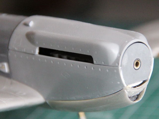
The result looked good.
Now I taped the side engine panels into place. They lined up well with the outer edge of the propeller mounting plate but there was a slight mismatch at the bottom of the propeller mounting plate. The top engine cover aligned well so I decided to work with this small misalignment as everything else was looking okay.
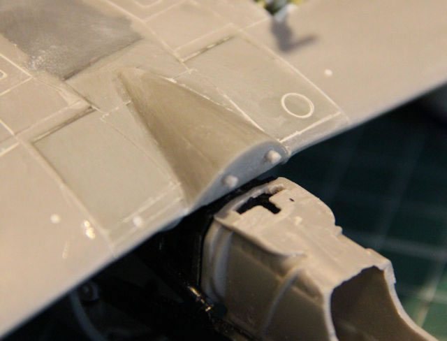
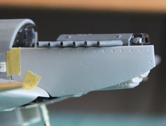
Using thin cyanoacrylate, I fixed the side panels in place. The carburettor intake section was offered up and the fit at the propeller mounting plate was reasonable but at the wing root end it was obvious that the carburettor intake was about 1mm too wide. I was concerned that I might go through the edge lip if that amount was taken off. The solution was to add material to the inner edge of this lip by fixing a strip of plastic card to the back of the lip. It was also obvious that the forward lip was about 1mm proud of the outline of the propeller. Rather than try to reduce the depth of the of the intake and maintain the interface with the side panels, it would be easier to reshape the profile of the carburettor intake where it joined the underside of the wing.
The air intake was gradually thinned down until it was within 0.25mm of the side panels and the curvature of the mating face was adjusted to suit the lower edges of the side panels. The joint to the lower wing centre section ‘T’ piece was out by around 1mm on one side and was somewhat ‘wedge shaped’. I attached a section of 1mm styrene sheet to the rear face of the intake and filed it to match the face on the lower wing centre section ‘T’ piece. The intake was taped in position and, using cyanoacrylate, it was fixed to the lower wing and bottom of the propeller mount. There then followed much careful sanding to get the intake to match the profile of the side panels and the portion of the trunking on the wing lower panel. I was able to achieve this on all but the starboard side where filler was needed to fix a small step in the joint to the wing lower panel. The addition of material to the inner edge of the lip proved to be a good idea. The plastic was visible through the resin after sanding!
To get the exhausts slightly above the edge of the side panels 0.5mm strips were attached to bottom of the cylinder head/exhaust assembly. This was then glued into place and the top engine cover was attached.
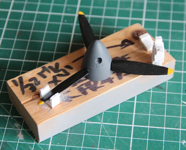
The next job to tackle was the propeller assembly. I recall from the Airfix 1/48th kit that, unless great care was taken during assembly, the blades would not be in the correct orientation and could look somewhat ‘squiffy’! I drilled both the propeller hub and the blades and used short lengths of brass tube to make a more robust fixing system. Using sleeved plastic tubing, I made a drilling bush that fitted into the blade apertures on the propeller and another to fit over the stubs of the blades. This ensured that pilot holes could be drilled as close as possible to the centres of each and along the centre line of both the apertures and the blades. The blades were drilled whilst still on the casting block as this made for easier handling.
A assembly jig made for an earlier 1/32nd Spitfire was modified for the Seafire propeller. This ensured that (1) each blade would be perpendicular to the propeller axis and (2) would be set to the same incidence.
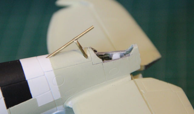
I built a new ‘roll-over’ guard to fit behind the headrest and the upper fuselage was drilled to take a section of tube for the filler neck. These were attached.
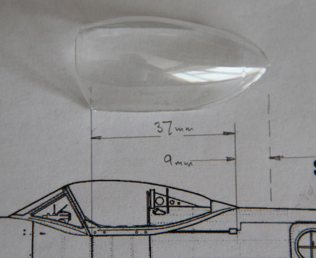
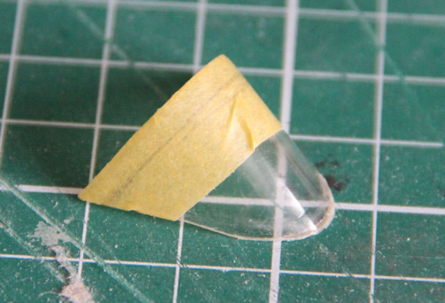
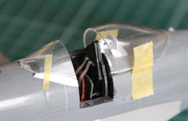
The next task was to trim the vacuum formed canopy and windshield. This proved more difficult than others I have trimmed as the material, although exceptionally clear, was quite thick. After a slip with my scalpel that resulted in having to quickly find a plaster, I resorted to taping up the parts and carefully cutting with my Dremel. Once trimmed and sanded to the guidelines, the parts were offered up to the fuselage. For some reason I cannot fathom, the windshield seemed to be far too wide to fit to the fuselage without a lot of pressure and it did not look right when taped in position. The canopy looked to be similar. Using the drawings in SAM Publications Modellers’ Datafile #5 Griffon Powered Spitfire publication it appears to be 9mm too long and both that and the windshield seemed very tall. Lots of cutting and trimming was required to get them to look more in line with the drawing. I trusted the drawing!
Dear Freightdog: if I was wrong, please tell me what I should have done!
I attached stronger windshield side plates to retain the modified windshield.
The ailerons had been removed and the odd shaped bulges on those and the wings were removed and replaced with narrower ones and then reattached to the wings with a small deflection. The small scoop on the upper engine cover was removed and replaced with one modelled as on the plan. The ‘slinging points’ on the forward fuselage were also removed and replaced with styrene sheet and brass tube. New ‘bulges’ were made and attached above the undercarriage locations. These also covered up the ends of the brass tubes through the wing.
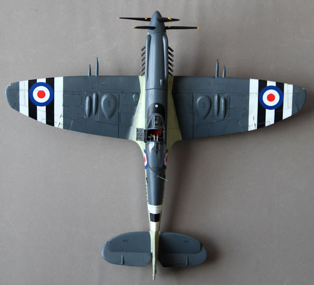
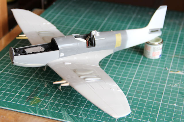
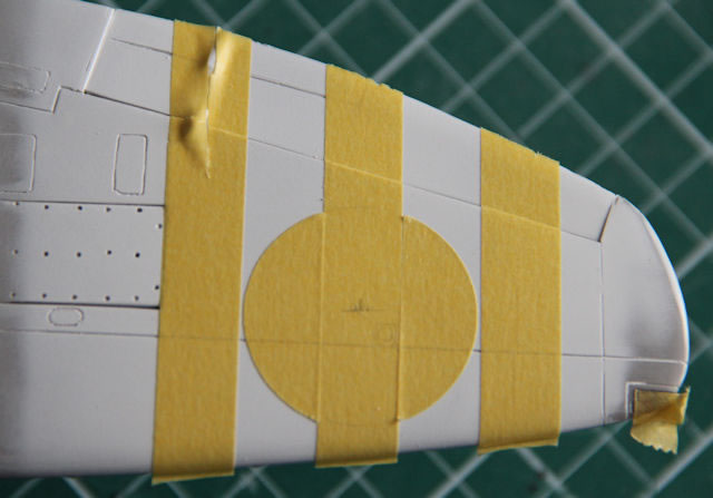
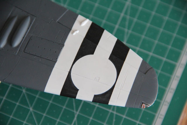
Once this was done. I used Halford’s Universal White Primer to spray where the Korean War identification stripes were to go. Masking was strips of card bent to a shallow ‘V’ shape and taped to wings and fuselage to ensure a soft edge. The rest of the airframe was enclosed in a plastic bag and taped to the strips of card.


Torque links which are on the rear of the undercarriage legs (thank you chek_16! on HyperScale’s Forum, without your help I would not have realised they were the same as the Mk. 24) were made and attached to the legs. I made them from 0.7mm thick styrene strip. This is somewhat over-size, but they will not be seen from side on, so I was happy with that. The doors were then attached to the legs.
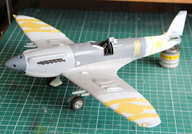
Now it was just a matter of painting!
The Matchbox variant of this kit is moulded in two shades of grey (I believe that the Revell version is all in one colour). Spraying white on to the airframe makes that contrast extreme! Where the Sky was to go, I should have painted an undercoat of grey to match the lighter of the kit’s greys. The transition of light grey to white took three coats of Humbrol 90 to make invisible. Freightdog’s instructions state that the remainder of the airframe was in Extra Dark Sea Grey. This is at variance with Modellers’ Datafile #5 that implied that Dark Sea Grey was the norm by 1950. Freightdog’s sheet quoted Tony O’Toole as being part of the team. Tony had helped me with a conversion of the Hasegawa 1/32nd Spitfire Vb to a ‘Hooked’ Seafire so I trust his take on the colour scheme. EDSG it was then. I used Phoenix Precision Paints EDSG. These paints are particularly good, but they are ‘hot’ and begin to ‘skin over’ very quickly when brush painting. You must work quickly, panel by panel, to maintain a good finish. I keep a pot of thinners nearby to occasionally remove thickening paint from the brush. I did not want to risk the black and white Korean War stripes showing through the wing roundel decals, so the masking was cut to keep that area white.
They say thinks happen for a reason. I am sure that this will resonate with many modellers! Whilst trying to position the second of the tailwheel doors using a pair of tweezers. I applied too much pressure and off it flew into the depths of one corner of my study where two shelf units meet. The part hit the wall and bounced of out of sight with two audible ‘clicks’ as it hit objects in its flight path! I spent the rest of the day unloading each shelf to see if it was hiding there. In the end all the shelves were removed with no luck and then I resorted to using the vacuum cleaner to gather up everything that was lurking in the dark recesses of that corner. I carefully emptied the dust canister on to sheet of paper. Still not there!
My wife’s friend, when she was told of my efforts including vacuuming the study floor, said “you can give the part back to him now!”
I decided to make a new door. When I looked at the plan and compared it to the remaining kit door I realised it was nothing near the correct shape. So, TWO doors were required. I found the tail section of the PCM Mk 16 that I had converted, glued the two halves together, fabricated and fixed a new ‘blister’ to where the tailwheel doors were and let it dry overnight. I then sawed the rear of the fuselage along the centre-line and took out the sections to make new doors.
I had already drilled the Seafire’s rear fuselage for the tail-wheel guard. Using three lengths of 1mm diameter brass tube, I constructed the guard. The tailwheel section was also reshaped to suit the new doors.
Apart from all the above, the rest of the build was straightforward!
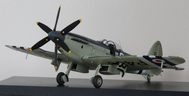
The remainder of the painting was achieved using Humbrol for the Sky, black anti-glare section and Korean stripes and Phoenix Precision Paints for the Extra Dark Sea Grey.
The finished paintwork was given two coats of gloss varnish and allowed to harden before applying the decals.
The windshield and canopy were both dipped in ‘Future’ after painting and attached.
The decals were by Fantasy Printshop and were superb. The 800 Squadron crest on the cowling was ‘constructed’ from 3 separate decals: one blue, one gold and one black. A real eyesight test, but the finished result was great.
The underwing serials had to be cut to suit the undercarriage doors and the Korean War stripes but one portion, after being applied with Mr. Mark Setter and pressed down, decided to curl up into a small ball when Mr. Mark Softer was applied. This was the only problem I had but it required some careful mask cutting to reapply the lower part of a zero to the wing!
Some panel wash was applied to give the airframe a slightly ‘used’ look and then matt varnish applied.
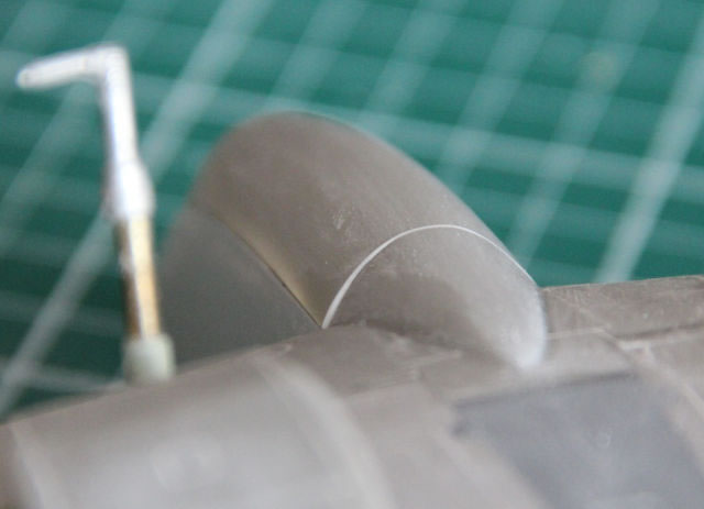
Aerial, pitot unit and underwing pole aerial were fitted as a last operation.

I am not sure if, in reality, all three cameras were fitted at one time, but I had so much fun making them they all went in. So, there is a camera visible whichever way you look at the finished article.
Model, Images and Text Copyright ©
2020 by Ken Stanton
Page Created 8 September, 2020
Last Updated
8 September, 2020
Back to HyperScale Main Page

|
 Home
| What's New | Features | Gallery | Reviews | Reference | Resource Guides | Forum |
Home
| What's New | Features | Gallery | Reviews | Reference | Resource Guides | Forum |