|
Classic
Airframes'
1/48 scale
Supermarine Walrus
by Chas Bunch
|
 |
|
Supermarine
Walrus |

Classic Airframes'
1/48 scale Walrus is still available online from Squadron.com
I had this kit in my stash for quite a while before finally getting
to it. I'm a big fan of Classic Airframes, as they are the only source
for some of my favorite subjects in my scale.
I was intimidated by this one at first because of the engine hanging
on struts between the top and bottom wing, but after reading
John C. Valo's Walrus build article here on HyperScale, I decided to
get on with it.
 I
began this project by amassing all the information in the way of photos
and drawings from any source I could - mostly the internet - as the kit
instructions were pretty vague in some areas. I
began this project by amassing all the information in the way of photos
and drawings from any source I could - mostly the internet - as the kit
instructions were pretty vague in some areas.
I started construction with the interior. I dressed up the panel with
Mike Grant instruments and added some goodies to the cockpit from
photos. Then I joined the fuselage halves.
Next, I thinned the trailing edges of the wings and tail surfaces. I
inserted a brass tube for a spar in the lower wings to fit in a hole I
drilled in the wing root of the fuselage for added support. At this
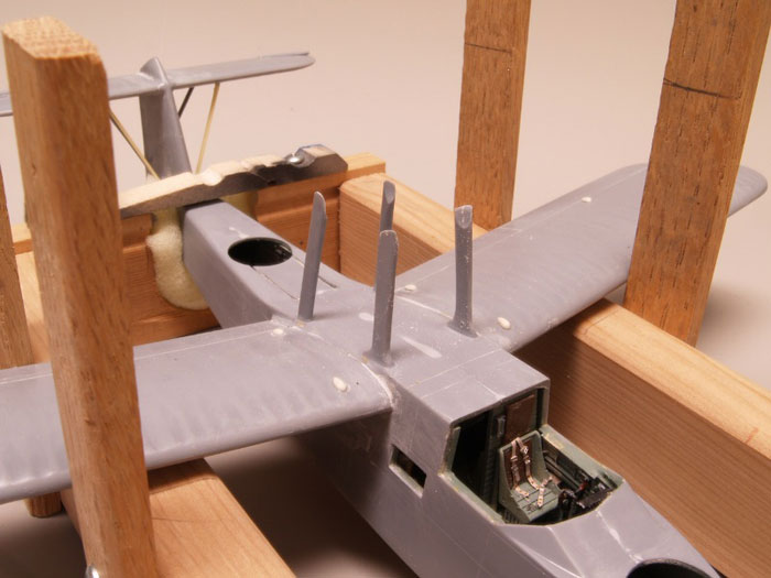
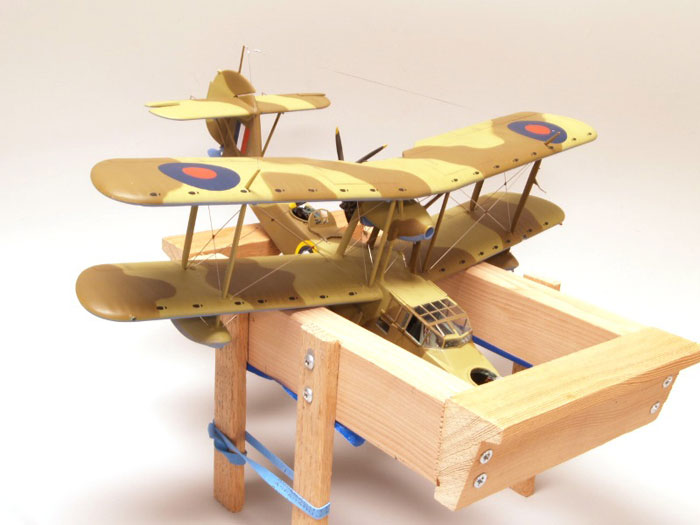
point I realized that I would need a construction jig to keep everything
in alighment, so I built a cradle from wood scraps to hold the fuselage
level and installed the lower wings with 4 degrees of dihedral. The
wing roots needed a little filler and sanding to take care of some small
gaps.
Next were the tail surfaces. I cut off the elevators and drooped them,
as photos all showed drooped elevators on the ground. I had to make new
stabilizer support struts, as the kit struts were too short. I made the
struts by squeezing aluminum tubing in a smooth jawed vise, then filed
it to a streamlined shape. I made a rudder trim tab per kit
instructions, and added a tail nav light per photos. The kit
instructions do not mention nav lights, landing light, mooring rings,
pitot tubes, or many other details I ended up scratch building from
photos and drawings.
Then the top wing. I taped the center section to a flat surface and
attached the outer panels by using shims under the tips to give it 4
degrees of dihedral, then taped it in place to dry.
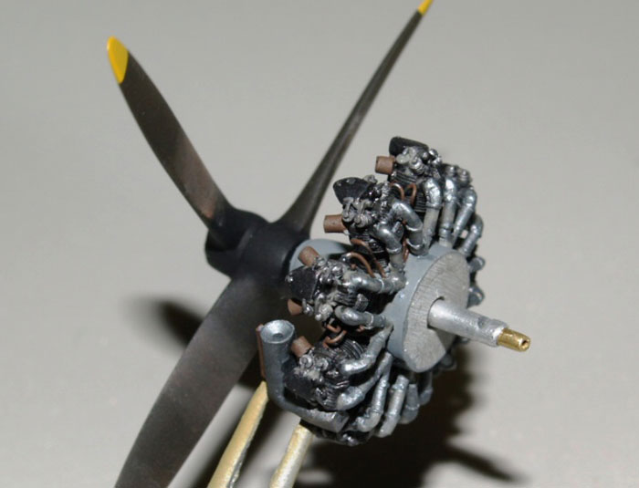
I then painted and detailed a Quickboost resin engine. The kit engine
lacked the great detail that Quickboost offers, from intake tubes to the
finest detail of individual valve springs. I added ignition wires to
the stubs representing spark plugs and exhaust stubs from styrene
tubing. I also drilled out the center and installed a piece of brass
tubing, and installed a brass rod on the prop for a free-spinning prop,
and crimped a short piece of tubing on the forward end to hold it in
place.
Now the fun part - getting the wings on straight with the engine in
between. I set the hull and lower wing assembly in the jig after
drilling small holes in all the strut locations. I then drilled the
ends of the struts and inserted short stubs of wire to assist in holding
them in place during assembly. I put the engine support struts in place
and temporarily taped them down to dry fit the engine nacelle with the 5
degree offset to starboard, cutting and shaping the struts to fit. Then
I taped the nacelle to the struts and set the top wing in place in the
jig, using the inboard wing struts to get the correct height. I then
dry-fitted the braces between the top of the nacelle and top wing center
section. Once I was satisfied that everything would fit, I cemented the
braces to the center section. Once dry, I removed the top wing, drilled
holes at the approximate correct angles for all the rigging wires, and
painted and decalled the top wing, engine nacelle, and hull and lower
wing assembly.
Then I installed the engine nacelle to the center section and added
the rigging wires and fuel lines between the sump drains and nacelle.
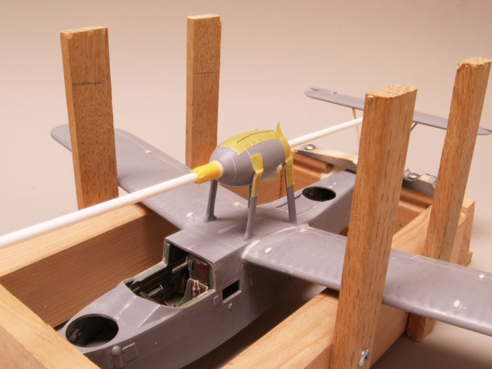
Then, the hull went back into the jig. I installed the rigging wires
between the engine support struts - hard to do later with the top wing
on.
Next, I set the top wing in place and epoxied the nacelle to the support
struts, and glued the wing struts in place - an easy task with the wire
stubs in the previously drilled holes. Once dry, I removed the model
from the jig and had a biplane ready for rigging.
Rigging was done with .009" stainless steel wire. The previously
drilled holes were slightly oversized to give me some wiggle room to
prevent binding and kinking. Once each wire was in place, a drop of CA
glue held it. I found the jig (more like a cradle) useful to hold the
model in various positions while rigging and attaching small parts like
antennas. Also, great for transporting the model without breaking
fragile stuff.
Click the thumbnails below to view larger images:
[../../photogallery/photo00030297/real.htm]
At this point I attached the engine and prop to the nacelle, and
discovered that the prop tips would not clear the top of the fuselage.
The choices were to cut a groove in the fuselage, shorten the prop, or
raise the engine. I raised the engine a couple of millimeters and
nobody knows the difference.
I decided to open the side windows, so I carefully cut them off the
canopy with a razor saw, leaving the frames on the main canopy intact.
I made new frames for the side windows from styrene strips to replace
the material removed by the razor saw, and made rails for the side
windows from photos. I found that the canopy had a small gap at the
front of the windscreen, so I added a piece of styrene strip to the rear
of the canopy for a shim, and it was a perfect fit. A little paint
touch up with a brush took care of the shim.
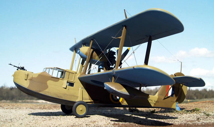
I used Testor's Model Master paint and kit decals.
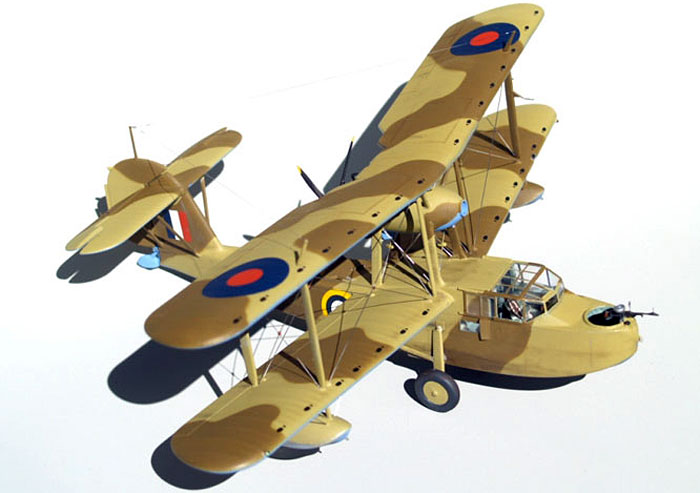
I chose the desert scheme from a unit in Egypt just because I thought
it would be different - a flying boat in the desert.
Click the thumbnails below to view larger images:
[../../photogallery/photo00021912/real.htm]
Model, Images and Text Copyright © 2007
by Chas Bunch
Page Created 19 November, 2007
Last Updated
24 December, 2007
Back to
HyperScale Main Page
|
 Home
| What's New |
Features |
Gallery |
Reviews |
Reference |
Forum |
Home
| What's New |
Features |
Gallery |
Reviews |
Reference |
Forum |