|
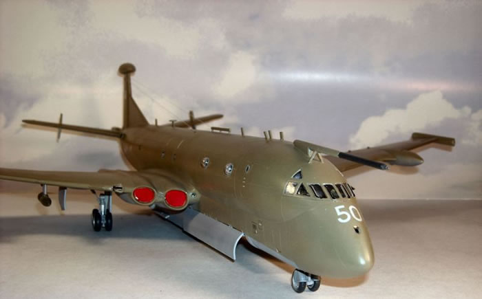
Airfix's 1/72 scale
HS/BAe Nimrod
by James Kelly
|
.jpg)
|
HS/BAe Nimrod |

Airfix's 1/72 scale Nimrod is available online from Squadron.com
The Nimrod is a maritime patrol aircraft developed in the United Kingdom, dating back to 1968. It is an extensive modification of the de Havilland Comet, the world’s first jet airliner. It was originally designed by de Havilland’s successor, Hawker Siddeley, now part of BAE Systems. A major modification was the fit of a large weapon bay under the fuselage that can carry and drop torpedoes, mines, bombs and other stores. Sonobuoys for tracking submarines are dropped from special launchers in the rear of the fuselage.
It has been the Royal Air Force’s primary Maritime Patrol Aircraft (MPA) since the early 1970s, when it replaced the piston-engined Avro Shackleton. The RAF uses two Nimrod variants: the MR2 variant in the Maritime and Reconnaissance role; the R1 variant in a reconnaissance and electronic intelligence gathering capacity (ELINT).
The Nimrod was the first jet-powered MPA of any significance. Earlier MPA designs used piston or turboprop engines to improve fuel economy and allow for lengthy patrols. Jet engines are most economical at high altitudes and less economical at low altitudes. However, the transit to the operational area can be made at high altitude and in a jet aircraft this is not only economical on fuel but fast as well, compared to earlier piston-powered aircraft. After transit, the Nimrod descends to its patrol area.
On patrol, at high weight all four engines are used, but as fuel is used and weight falls, first one engine is closed down and then a second is closed down when weight is lower. This allows the remaining engines to be run at an efficient RPM rather than running all engines at less efficient RPM. A special “rapid start” system is fitted should the closed-down engines have to be started quickly again. Instead of relying only on airspeed for re-starting an engine, compressor air from a live engine is used in a starter turbine which rapidly accelerates the engine being started. For transit back to base, the closed-down engines are re-started and the aircraft climbed to altitude.
This new Airfix release has been much-anticipated by many, and it shan’t disappoint. The molding of the 249 parts is first-rate. A few parts have visible pin-ejector marks, namely, the main undercarriage gear, crew and weapons bay doors. These are easy to remedy. The rest are thoughtfully engineered away and out of site. The decal sheet, as you may have heard, leaves much to be desired. Although all stencils and markings are provided for several machines, the large subjects, especially the roundels, are clearly “pixallated”. To make matters worse, all subjects are covered in two layers of film; The “varnish” layer, closely cropping each subject, then a thin, overall layer that covers the entire sheet! In applying the instrument panel decal, I learned the very hard way that EVERY decal, like home made ALPS decals, must be cut to the exact image to avoid a huge overlap of carrier film. Putting all of the hundreds of stencils on this thing will not be a pleasant task.
I picked up my kit at the Three Rivers IPMS Annual Invitational during the last weekend in March, and began work on it immediately. I am not a huge fan of British aircraft, but the buzz surrounding this release was positive, and it’s one of those aircraft that are so ungainly and unattractive, that they’re beautiful. I must admit…this thing is already really growing on me!
The build was extremely enjoyable, and relatively easy. The cockpit is sparse on detail, but when all is said and done…you won’t see much anyways. The color callouts are simple numbers that correspond to Humbrol enamels, as is usually the case with Airfix directions. No reference is provided, but IPMS Stockholm has the list available on their website. The three aircrewmen were painted, and cemented to their duty stations. The interior of the fuselage has slots for the bulkheads to fit into, allowing perfect alignment of the crew deck and the weapons bay. The directions show that 20 grams of weight needs to be added under the cockpit area, and I cemented as much lead as I could fit into that space (using cyanoacrylate).
The build was extremely enjoyable, and relatively easy. The cockpit is sparse on detail, but when all is said and done…you won’t see much anyways. The color callouts are simple numbers that correspond to Humbrol enamels, as is usually the case with Airfix directions. No reference is provided, but IPMS Stockholm has the list available on their website. The three aircrewmen were painted, and cemented to their duty stations.
.jpg)
The interior of the fuselage has slots for the bulkheads to fit into, allowing perfect alignment of the crew deck and the weapons bay. The directions show that 20 grams of weight needs to be added under the cockpit area, and I cemented as much lead as I could fit into that space (using cyanoacrylate).
.jpg)
The nose gear well fits snugly into place. Since I do not use enamels, I am substtuting Vallejo Model Air colors for the Humbrol suggestions. Instead of RAF Light Grey on the gear, I used Vallejo’s Light Grey (050). I painted all of the clear parts with Future Floor Polish, and let dry overnight. The next day, I installed them into their respective portholes. be advised, when inserting the windows into the portholes running the length of the fuselage, that the holes must be lightly sanded. Otherwise, the clear parts don’t fit. The fuselage went together easily, was cemented with Tamiya Extra Thin liquid cement, and allowed to dry overnight.
I took off the clamps and rubber bands, and wet sanded the seams. I started with 220 grade wet-dry sandpaper, and progressed through 800 grade. Then I switched to Micromesh polishing pads, 1500 grade through 4000. The four jet intakes were assembled, sanded, and painted Tamiya Flat White (XF-2). I’m pleased to say that at this point, no putty has been used at all. Everything seems to fit marvelously, and it’s been an extremely enjoyable project, so far. After completing the main construction of the fuselage, the directions have you build the jet engine’s intakes. Two simple, cylindrical parts with a compressor face. Generally, I’ll coat the inside of a jet intake with Tamiya putty, then smooth it out with Tamiya liquid cement, and finish off the interior with several grades of sanding paper, but not this go-around. The parts fit neatly together, and enough plastic “squished out” of the interior seams from the cement so that I was able to simply sand them flush. These assemblies then fit into the nacelle area of the wings.
The main gear wells are over simplified, consisting of a basic frame to be cemented to the upper half of each wing, around a bit of molded on detail. The fit is good around the detail area, but the butt-joint isn’t flush with the lower wing halves, and will need some stock styrene sheet or putty to fill in.
.jpg)
You’ll note from the photos that the wings used every clamp that I have! The two sets of main flaps are assembled here, as well, and will be posed in a slightly “dropped” attitude. One thing I feel I have to comment on is the overall fit of the parts. The fuselage and wings have seated together so well, that so far no putty or filler has been used. Yes, there’s a small gap, as mentioned, with the main gear well/wing join, but the basic fit of parts is superb. Test fitting of the wing to the fuselage found that it seats flush with an audible “click”. We’ll soon see how that plays out once cement is applied, but it bodes well!
The wing assemblies are sanded smooth, and attached to the fuselage. The entire subassembly went together without trouble. There was a little bit of “fiddlyness” on the forward, port-side edge of the wing/weapons-bay join. A touch of Tamiya putty fixed it fine. Any seams along the forward edge of the wings were touched up with cyanoacrylate and sanded/polished. I am pleased to report that the wingroot/fuselage joint requires no filler. After filling the seam with Tamiya Extra Thin Liquid Cement, I ran a length of tape from wingtip to wingtip to maintain dihedral, and this sealed the butt joint. You will note, from the photos, that the resultant gaps inside of the jet
.jpg)
trunking assemblies are fairly significant. A lot of extra time could be spent here fixing this, but I will spend less time creating FOD covers to blank off the intakes. The weapons bay, with nicely-engineered pressure flooring, doesn’t have much in the way of details…but, once fully loaded, or closed up if you so choose, it’ll be pointless. A super-detailer could have a field day adding details, but again…with a full load and the plane’s low stance, it will go largely unseen.
One interesting note concerns the instruction booklet, most specifically steps 15 and 16. These steps concern the horizontal stabilizers. The instructions call for parts 17C & 18C to be cemented together, forming the port-side “stab”. However, this is incorrect. The insertion tabs molded into these parts are such that the characteristic dihedral of the Nimrod’s stabilizers are “built-in”…however, as depicted, the tabs on 17C & 18C oppose one another, rendering the join impossible. The correct assembly sequence should be parts 17C to 19C, and 18C to 20C.
.jpg)
Once assembled, the flaps install without trouble. I covered the observation windows with Tamiya tape, and the oval cabin windows with a yellow, “Blu-Tac” type of putty. Then, holding the tail-end of the model, I coated the rest of it with Tamiya Grey Primer (in a rattle can). Although there is a fair amount of parts left to be attached to the fuselage, I wanted to check the overall surface for flaws. Tomorrow, I’ll attach the horizontal stabilizers, and prime the aft end of the model.
As you can see in the photos, the fit of the horizontal stabs is poor. As my friend, expatriated Brit Paul Bradley, put it, “The fit doesn’t look very clever.” Umm…not so much. The gaps on the undersides were filled with stock styrene rod, and the tops were dealt with largely with Tamiya putty. The starboard stab got a length of stock rod towards the front, as the gap on this side was wider than the port side. After lots of sanding and polishing, I sprayed the aft of the model with Tamiya Grey Primer. I was pleased to see that the efforts paid off.
I also went over the surface of the model with Micromesh polishing pads. Additionally, I assembled all of the wheels. Much to my chagrin, I dropped one of the wheel halves, and despite spending a significant amount of time looking for it, had to take one out of a second kit. I really hate doing that. Hopefully, it’ll surface, and can go back into the donor kit. The nosewheels (2) have a large pin ejector mark on the outward-facing surface of the wheel housing. I touched each with a dab of putty, and filed/sanded flush. When installing the jet engine’s exhaust cans, the rear nacelle that houses each of the outboard engines on each wing split back open upon installation. This was sanded down, and resurfaced with putty. It seems that despite all of the major assemblies going together with no filler, I’m making up for it with all of these minor issues cropping up, and requiring it. Still, considering the size of this model, I’d rather do things this way, than have to use it on the fuselage seams or wing roots!
One other thing I did concerns the starboard wing searchlight. Being that the searchlight dome is fairly large, allowing everything behind it to be seen, I modified it slightly. I simply punched out a disc with my punch/die set, and cemented it over the open end of the light housing. Then, I painted the housing black, and the disc I made silver. Then, the clear housing was cemented in place. This will provide a small amount of visual interest if anything is to be seen inside of the searchlight housing. The rear nacelles were sanded smooth, and the obliterated lines rescribed.
I added all of the fiddly antennae, and filled a couple of unneeded holes on the fuselage (behind the cockpit). After these were sanded flush, I completed the main undercarriage. The wheels are a sloppy fit to the mounting pegs, and care must be taken to align them properly. Another note of caution: when assembling the main gear, Part 23 is mislabeled in the instructions as Part 29. It’s an easy part to recognize, but all the same, beware. I hope to have this beastie painted by the end of the weekend, and have the weapons bay full of stores. That will leave only the myriad of crappy decals to contend with (!). You may have noticed, the putty balls are off of the windows. I picked up a new bottle of MicroMask solution, and coated all of the windows with it.
After fussing with the horizontal stabilizers, and finishing up surface preperation, I primed the model with Tamiya Grey Primer straight out of the rattle can. Then, I polished the whole thing again with 8000-grade Micromesh cloth. I have, of late, been foregoing the commonly-seen pre-shading on my models. I’m not sure why, may I just wanted to get away from it…But after the primer was applied and polished, I airbrushed the lower surfaces with Vallejo Model Air Light Grey (050). After this dried overnight, I masked off the lower demarcation lines, and applied V.M.A. Hemp (023).
Once this was done, the entire model was sprayed with Future floor polish, and set aside to dry overnight. I cemented the main landing gear to the model. This required some light sanding of the fore and aft portion of the proximal main shaft. The fit was still very snug, so be careful not to push too hard and break the gear. Patience will pay off here. I also cemented to wheels to the nose gear. Their fit is very sloppy. I noticed, after they had dried, that I had the fenders rotated too far forward, as they should be at the ‘back” of the wheels. Oh, well. They’re straight, and I’m not pulling them off and starting over!
The weapons loadout for decal option “D”, the “Maid of Moray”, were assembled next. This consists of 3 Stinger torpedos, 4 racks of depth charges, 1 AGM-84 Harpoon missile, and 3 yellow things. Sorry, but I have no idea what they are. These fit neatly into the weapons bay, which you can model open or closed. I opted for it to be open, hence the weapons assembly. All of the 4 doors have large, deep pin-ejector marks on the inner surfaces, which need to be filled. They were, then the doors were painted Light Grey. Two actuator arms on each door ensure proper opening stance.
.jpg)
The landing gear doors also have pin-ejector marks that need addressed. There are no positive locators for the gear doors, so they must be carefully cemented to the edges of the wells. The nose gear door is one piece, and if the gear is down, you must cut the door in half. Also, the instructions make no mention whatsoever of there even being a nose gear door, so be careful! Reference photos show that when the aircraft is on the ground, the nose gear doors are not perpendicular to the ground; they are opened to about 30-40 degrees.
The decals were not as poor as I had feared. They do need trimmed back to the varnish coating around each subject, but all went down easily with some Micro-Set or Mr. Mark Softer. Once they are applied, the detail painting was accomplished, and then the model received a final coat of Future to seal everything in. Airbrushing of some light weathering was achieved by “post-fading” the individual panels with a lightened shade of the hemp color, and then a Semi-Gloss coat was applied to the model.
Images and Text Copyright © 2008 by James Kelly
Page Created 17 January, 2008
Last Updated
17 January, 2008
Back to HyperScale Main Page |
 Home
| What's New |
Features |
Gallery |
Reviews |
Reference |
Forum |
Search
Home
| What's New |
Features |
Gallery |
Reviews |
Reference |
Forum |
Search_fs.jpg)
_fs.jpg)
_fs.jpg)
_fs.JPG)
_fs.jpg)
_fs.jpg)
_fs.jpg)
_fs.jpg)
_fs.jpg)
_fs.jpg)
_fs.jpg)
_fs.jpg)
_fs.jpg)
_fs.jpg)
_fs.jpg)
_fs.jpg)
_fs.jpg)
_fs.jpg)
_fs.jpg)
_fs.jpg)
_fs.jpg)
_fs.jpg)
_fs.jpg)
_fs.jpg)
_fs.jpg)
_fs.jpg)
_fs.jpg)
_fs.jpg)
_fs.jpg)
_fs.jpg)
_fs.jpg)
_fs.jpg)
_fs.jpg)
_fs.jpg)
_fs.jpg)
_fs.jpg)
_fs.jpg)
_fs.jpg)
_fs.jpg)