Hasegawa's 1/48 scale
Focke-Wulf Fw 190 A-4
by Scott Miller
|
|
Focke-Wulf Fw 190A-4 |

Hasegawa's 1/48 scale Focke-Wulf Fw 190 A-4 is avaiable online from Squadron
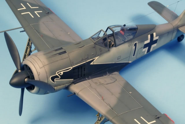
 This is the Hasegawa 1/48-scale Fw 190A-3 kit no. JT90, released in mid 2005. Although it is a 'new tool' kit, it is apparently based on the older Trimaster/Dragon tooling with improved engineering. Out of the box, the kit includes all the parts needed to do either an A-3 or early A-4 (and perhaps an A-2 with a little work); you get both vertical tail fin tops, two types of headrests (narrow or wide, check your references for which one to use), two types of horizontal tails, plus a bunch of extra later model parts that won't be used. Like the A-5 and later variants, some later model A-4's had engine cooling air exit doors behind the engine; this kit only includes the earlier open gills, but the later ones with doors are included in the Hasegawa A-4 kit (JT91). This is the Hasegawa 1/48-scale Fw 190A-3 kit no. JT90, released in mid 2005. Although it is a 'new tool' kit, it is apparently based on the older Trimaster/Dragon tooling with improved engineering. Out of the box, the kit includes all the parts needed to do either an A-3 or early A-4 (and perhaps an A-2 with a little work); you get both vertical tail fin tops, two types of headrests (narrow or wide, check your references for which one to use), two types of horizontal tails, plus a bunch of extra later model parts that won't be used. Like the A-5 and later variants, some later model A-4's had engine cooling air exit doors behind the engine; this kit only includes the earlier open gills, but the later ones with doors are included in the Hasegawa A-4 kit (JT91).
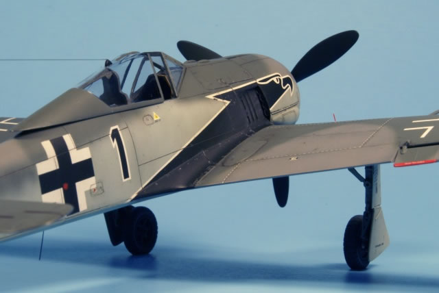
I had always wanted to do an early model 'Richthofen' Würger with the eagle's head motif, so for this build, I chose Black 1 of 2./JG2 using SuperScale sheet No. 48-853. This Fw 190A-4 was flown by Oberleutnant Horst Hannig, based at Triqueville, France, Spring 1943. His plane was brought down by a Spitfire near Rocquancourt on 15 May. He managed to bail out, but his parachute failed to open. Hannig scored 98 victories and was posthumously awarded the Oak Leaves to the Knight's Cross.
The build proceeded pretty much out-of-the-box with just a few enhancements. I generally followed the instructions and construction began with the cockpit. The cockpit tub, seat, instrument panel, and fuselage sides were airbrushed with Model Master RLM 66 Schwarzgrau lightened with white. Various details were then picked out in black, yellow, red, and blue according to reference photos. The cockpit was then given a dark brown/gray oil wash, and then dry brushed with a lighter gray. The instrument panel has raised detail for the dials, and the kit supplies a decal for all of the instruments. I attempted to punch out the individual dials, but didn't get the decals to lay down the way I wanted, so I removed them and just hand painted the details, then added Future to the dials. I added some paint chips and scuffing to the seat and cockpit floor with a silver pencil. Note that the instructions show the control stick backwards, so you'll want to make sure you have it turned around properly. The only additional item added to the cockpit was Eduard photo etched pre-painted seatbelts (49-002). The canopy crank was attached to the starboard side of the cockpit and this side areas of the fuselage was painted RLM 66.
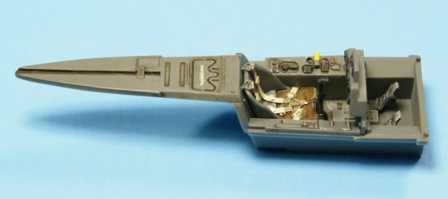
The instructions show the cockpit and tail wheel glued to the fuselage before gluing the two halves together, but I found that it was possible to glue them in later. Leaving the cockpit out at this time helped, because the fuselage halves were warped, particularly the starboard side, and not very well molded near the engine mount. I used Testors liquid cement and began gluing the two halves together starting at the cockpit coaming and working towards the engine mount, tightly holding it together with Tamiya tape.
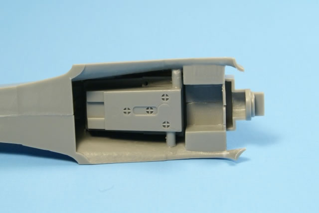
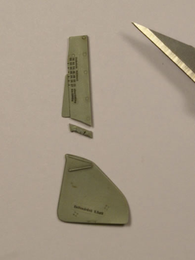
After the fuselage was glued together, the engine cooling air exit gill inserts were added. I lightly chamfered the edges with a file, to help preserve the panel lines after it's glued, since these were access panels. I thought about hollowing out these parts so that the cowling vents would be open, but ultimately decided to leave it alone and not risk it. The fuselage had a sink hole on each side near the tail wheel mounting, so these were filled with Mr. Surfacer 500 and sanded smooth. Next, the vertical fin tip for the Fw 190A-4 was attached with superglue (cyanoacrylate) glue. This is the most distinguishing feature between the A-3 and A-4 variants. The fin tip part was a bit thicker than the tail, so some material had to be removed with a sanding stick to make it flush. It also had some sink marks which had to be filled in.
Next, the engine mount was attached and then the upper machine gun cowling just forward of the cockpit was attached. This cowling required a fair amount of pressure with clamps and tape to get it to spread out a bit and get a good fit, as it was slightly narrower than the fuselage. With the fuselage in good shape, I inserted the cockpit from the bottom opening and glued it in.
I noticed that the rudder trim tab was a little on the thick side, so you may want to replace it with some thin sheet plastic.
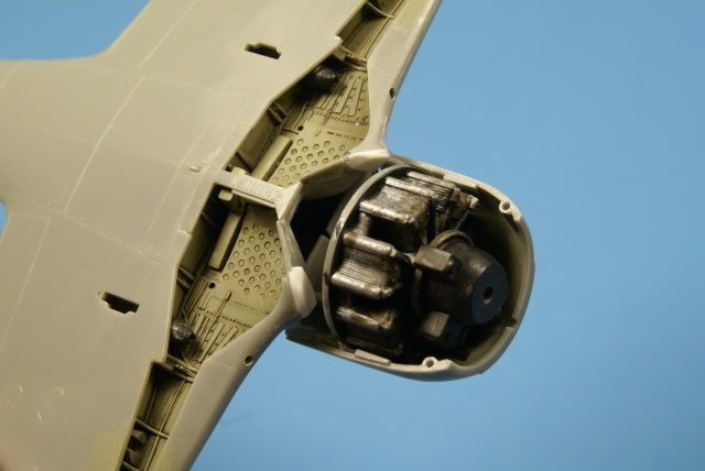
Wing assembly began with the single piece wheel well with integral wing spar to help ensure setting the proper dihedral of the wing; the landing gear leg mounting stubs are integral to the lower wing which greatly helps getting the legs positioned properly. The central frame and ammo chutes were attached, and then the entire wheel well assembly was sprayed RLM 02 Grau. I didn't have any pre-mixed RLM 02, so I mixed up a batch using Testors light gray, gunship gray, and olive drab while consulting the Eagle Editions Luftwaffe Color Chart as a guide. The wheel well painted areas were then brushed with Future and later dirtied up with a dark brown/gray oil wash.
Before attaching the wheel well/spar to the lower wing, I removed some material from the mating surfaces to improve the fit. Next, I opened up holes in the leading edge of the upper and lower wing halves for the cannon barrels. I elected not to use the boarding ladder, so I didn't open up the two holes shown in the instructions. The center panel was then glued onto the lower wing to separate the wheel wells. I found that this part needed to have some material removed along with part of the wing spar to get a nice flush fit.
At this point, I went ahead and attached the MG FF access doors to both lower wings. Again, some test fitting and material had to be removed from these parts to get a flush fit with the wing. I left the panel lines around this part, but filled in the streamwise join lines between the forward wing panel and leading edge of the access panel.
The ailerons are provided as separate parts. I would normally welcome separately molded control surfaces, particularly horizontal tails, so you have the option to pose them deflected. But in this kit, the aileron thickness is substantially thinner than the wing. This means that if left in a neutral position, there will be gaps and mismatch that really can't be fixed. I decided to slightly deflect mine to help hide this. I felt better about my decision after seeing many Fw 190 photos with slightly deflected ailerons. Since the ailerons didn't have a very positive mounting in the wing, I left them off until it was time to paint so they wouldn't get accidently knocked off.
Compared to the Trimaster/Dragon Fw 190 kits, Hasegawa provides a 'false floor' molded onto the bottom fuselage just aft of the cockpit. This may have been done to improve wing/fuselage fit, but I still had significant gaps at the wing root. However, a little dry fitting and a couple of pieces of sprue wedged and superglued between the cockpit and inside fuselage minimized the gaps. I also added some pieces of 0.020 inch plastic between the gear well and upper wings as shims to get flush alignment at the wing roots. This introduced a slight gap at the leading edge wing fillets which was filled with more pieces of 0.020 inch plastic. After gluing the wings onto the fuselage, I filled the wing root areas with a few careful applications of Mr. Surfacer 500, then rescribed the appropriate panel lines.
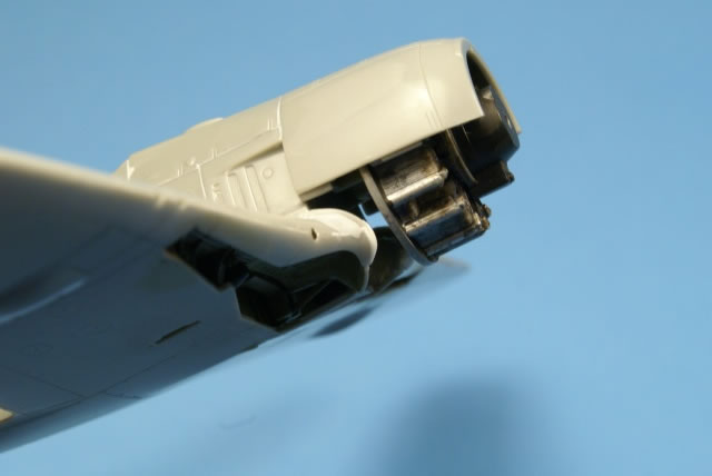
The adequately detailed BMW 801D-2 engine was sprayed with Floquil Old Silver and pushrods were painted semi-gloss black. Next a dark oil wash was applied to flow into the recesses to bring out the cooling fin detail. The gear housing, magneto, and Kommandogerat (control unit) were all painted flat black. However, the engine detail is not real visible when the cooling fan blade and propeller are added to the already narrow opening of the armored cowling ring.
Now for the fun part... the engine cowling! The kit instructions provide a six step assembly for the engine, exhaust, and cowling parts. I followed this order, but the fit of the five piece cowling was a little tricky. I first taped the cowling parts together to check the fit of the parts and to see how the assembled cowling would fit to the fuselage/wing... it didn't look good, particularly around the wing fairing. First, the exhaust banks were glued to each side of the upper cowling and one to the lower cowling. Next, the bulged cowling pieces were carefully glued to each side of the lower cowling. Before the glue set, the upper cowling was dry fitted to the lower cowling; this kept the bulged pieces in alignment with the two cowling halves while they dried. Next, the engine was glued to it's mount with 5 minute epoxy; since the cowling halves are also glued around the engine, I wanted a good strong bond. Dry fitting the upper cowling, I noticed that it didn't fit flush with the gun cover, so I sanded off some material from the 'shelf' in front of the gun cover and it's mating surface on the upper cowling. Satisfied with the fit, I again used 5 min. epoxy to attach the upper cowl to the engine and fuselage.
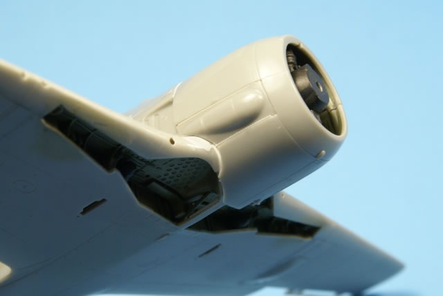
Now, it was just a matter of coercing the lower cowling in place. First thing I noticed was that it didn't fit, and the cutout curved shape around the wing fillet did not have a smooth radius like it should. I used an x-acto blade to carve out a curved shape and also thin the curved edge until the cowling fit properly.
This left a gap on the on the wing fillet which was filled with a couple pieces of 0.020 inch plastic which was attached together with cyanoacrylate, then sanded to shape. After the lower cowling was attached, I attached the armored cowl ring (oil cooler) which fit nicely.
On all of the panel lines created by the insert parts, I brushed on Mr. Surfacer 1000, and then used a cotton bud dipped in 91% isopropyl alcohol to remove the excess. This leaves a panel line depth more consistent with the molded recessed lines. I did find some inconsistencies with the depth and width of some of the other recessed panel lines on the fuselage which you may want to improve. The Hasegawa kit has the rear jacking points (aft fuselage just forward of the horizontal tails) represented as open holes. However most photos show that these holes for the lift tube inside the fuselage were usually kept covered, and I chose to plug mine with plastic rod, leaving it slightly recessed in the hole.
To finish up the basic airframe and get it ready for paint, I modified the Revi gunsight by removing the overly thick reflector and replacing it with a thin piece cut from clear plastic sheet stock.
Next, the front windscreen and main canopy were masked with Tamiya tape, and the front transparency was glued onto the model, and a tape mask applied to the cockpit.
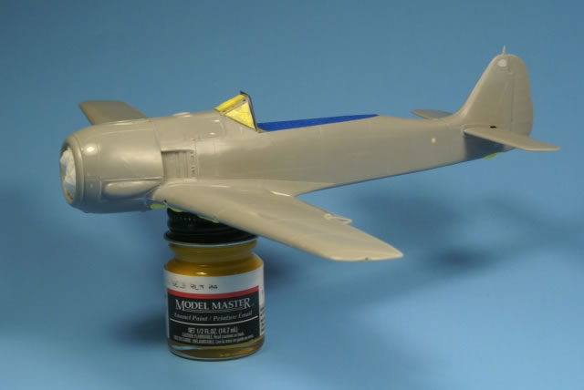
As near as I could determine and according to the SuperScale instructions, 'Black 1' was painted in the standard RLM 74/75/76. As shown on the one reference photo I found of this aircraft, it had a very light mottle on the fuselage sides and a little more on the vertical tail. I started off by spraying thinned Mr. Surfacer 1000 to check for seam problems and to get a uniform surface. I sprayed the RLM 04 Gelb on the lower engine cowl and rudder, and masked it with Tamiya tape after it dried. Next I sprayed some black to pre-shade panel lines and other areas.
For the main colors, I made some adjustments to the Model Master RLM enamels, using the Eagle Editions Luftwaffe color chart as a guide and my own "this looks about right". I used the RLM 76 Lichtblau out of the bottle but with a little white to lighten it. For the RLM 75 Grauviolet, I adjusted the MM paint with white to match the lighter shade/higher contrast between RLM 74/75 that can be seen in black & white photos. The RLM 75 on the EE color chart and the MM paint looked too dark. I adjusted the RLM 74 Graugrun by adding a bit more green and some flint gray to get it closer to the color chart. I thinned the paint more than necessary so that I could lightly build up the colors over the black pre-shading; later I added some random lighter shades to subtly show a variation in the completed paint job.
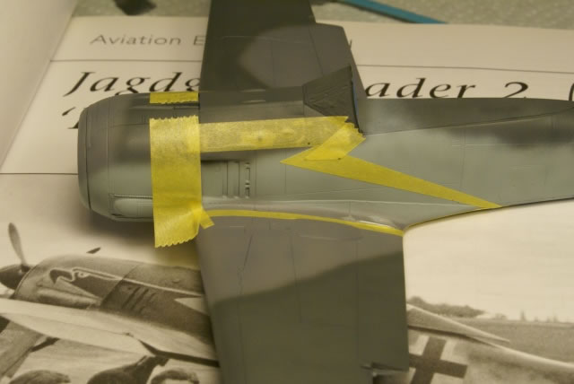
The provided eagle motif decal only extended down to the upper part of the wing fairing, even though the reference photo indicated that it extended onto the wing. I was further convinced of how far it extended onto the wing after seeing a photo from another JG2 aircraft (thanks Pat Donahue!), so I decided to mask and paint the portion aft of the engine cowl and not bother using the decal. I first sprayed white, then masked the outside portion for the thin border, then sprayed black (toned down with some white). While I had everything masked, I went ahead and sprayed some light exhaust stains (Testors rubber and gray) over the black. The bottom fuselage received some exhaust staining as well.
Satisfied with the paint job, I sprayed the whole model with a coat of Future to prepare the surface for decals. The decals went down nicely using Micro Set and Sol. I used some of the stencils from the SuperScale sheet and some from the kit.
After the decals had time to dry, I sprayed some more Future over the decals to get a uniform surface for the oil washes. I mixed up a nice brown/gray wash using Windsor & Newton burnt umber and paynes gray artist oils with turpenoid to emphasize details and dirty up the finish. In hindsight, I wish I had used a lighter/thinner wash on the side fuselage panel lines as these got a little over emphasized with the lighter RLM 76 paint. I'll blame that on the kit having wider panel lines than the more delicate recessed lines of my last Tamiya build!
For the final flat coat, I sprayed the model with Testors Dullcote mixed 50/50 with lacquer thinner. Paint chipping and scuff marks were made using Prismacolor silver and 90% cool gray. Artist's fine pigment pastels were used to further weather various surfaces and add further definition to the exhaust stains.
I had some questions about the operation of the landing gear and doors. While I was searching the internet, I found a great movie clip on YouTube which showed some black and white film of a JG 54 Fw 190A-4 captured by the Russians (http://www.youtube.com/watch?v=qayREUJe65w). This showed the operation of the aircraft in various flight phases, including the retraction and extension of the landing gear and doors, and a ground walk around. Not the best image quality and the narration is in Russian, but still very useful. Based on the normal operation of the undercarriage, I wanted to have the inner doors retracted. This required trimming some material off the edge in order to get a good fit.
The landing gear legs were cleaned with a sharp blade and sandpaper. The scissor links are molded separate from the gear legs and are overly thick. These were thinned on the inside with a sharp blade and a drill was used to open up the recessed holes. I added hydraulic lines to the main gear legs and three strands of wire to the upper radius struts to represent the micro switch wiring. A wire was also added to the starboard side radius strut to represent the tail wheel retraction cable.
The only real snag I encountered with the landing gear was the main gear leg covers. Hasegawa provides two parts for each side and instructs that the lower piece be attached by overlapping the upper piece. This didn't look right... in fact it looked really bad. To confirm, I check my references and pulled out my Eduard A-5 kit parts for comparison. The solution was to simply remove a slice from the overlapped portion of the upper door piece, and attaching the two parts with a butt join instead of the overlap. This looked much better and matched the dimension of the Eduard part.
I thought the tail wheel looked too tall when attached, so before it was glued in, I removed part of the strut to get something closer to my reference photos.
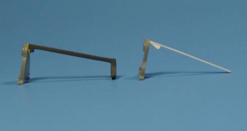
The nose mounted MG17 7.92mm machine gun barrels are molded into the gun cowl access panel. I opened these up using a pin vise and small drill bit during early construction of the fuselage. I also used the separately molded wing mounted MGFF 20mm cannon barrels and drilled these out as well. For the inboard MG151 20 mm barrels, I used 21 ga. stainless steel tubing. I didn't like the thought of trying to clean up the long pitot tube, so I used 24 ga. SS tubing inserted into 20 ga. tubing. These were glued up with Micro Kristal Klear.
The VDM metal propeller is molded as a single piece. After cleaning it up, I painted the hub and propeller mounts with Floquil Old Silver and the blades RLM 70 Schwarzgrun (mixed from RLM 80 and black). For the spinner, Hasegawa didn't include the characteristic center hole, so I drilled one and then painted it RLM 70. The fan blade was painted black and attached to the propeller and spinner assembly.
The main canopy assembly includes an armored headrest (I used the narrow one), and a headrest brace. I thought the brace was a bit thick, so I replaced it with one cut from 0.020 inch plastic sheet and detailed it according to references. I also added a black rubber canopy seal by sanding a flat side on a piece of plastic rod and attaching it to the face of the canopy. I wanted to have the canopy open, but the canopy was made for the larger width of the fuselage in the closed position and therefore it was too wide when in the fully open position (where the fuselage is more narrow). I decided to compromise and positioned it partially open. The Eduard Fw 190 kits provide two canopies for open (narrow) or closed (wide), which is nice feature.
Wing tip lights are provided as clear rods that you insert into preformed holes. I mixed some food coloring with Future to tint the lights; red on the left and green on the right. Note that the instructions indicate blue on the right, but I believe this is in error.
For the landing gear indicators, I used a #80 drill bit and opened up the appropriate holes on top of the wing. The rods were made of white stretched sprue with the upper part painted in red. Note that when viewed from behind (or from the front), the rods have a slight inward cant relative to the vertical.
I also drilled a hole on the bottom of the fuselage and added an AAG25 rod aerial (antenna) made of black stretched sprue. The upper aerial was sourced from invisible thread and attached with super glue. The ceramic insulators were made from Micro Kristal Kleer and painted a very light gray.
Overall, I really enjoyed this kit. It gave me a few challenges to work through and keep my interest up, but not so much as to become frustrating. And, I think it builds into a really accurate looking early model Würger.
Model, Images and Text Copyright © 2009 by Scott Miller
Page Created 30 April, 2009
Last Updated
30 April, 2009
Back to
HyperScale Main Page |
 Home
| What's New | Features | Gallery | Reviews | Reference | Resource Guides | Forum |
Home
| What's New | Features | Gallery | Reviews | Reference | Resource Guides | Forum | 


