Aeroclub + Hasegawa 1/48 scale
Seafire F (FR) Mk.17
by Ken Stanton

Hasegawa's 1/48 scale Spitfire Mk.IX is available online from Squadron
This is the third Spitfire related Aeroclub conversion I have built.
Previously I have used an F21 conversion to create a PRXIX (using ICM wings) and another F21 conversion for its intended purpose - using the spare FR 46 wings from the Airfix Seafire FR 46/47 kit.
For their Seafire 17 conversion Aeroclub recommend the Airfix Seafire Mk III, the Hobbycraft Seafire 15 or the Hasegawa Mk IXc kit for the donor wings.
I had both the Airfix and Hobbycraft kits but I did not care for the job of converting the Airfix ‘C’ wing to a symmetrical radiator configuration or to use the rather thick section Hobbycraft parts. I looked at the Hasegawa Mk IXc kit and decided that this was the best, albeit more expensive, option for this conversion. As you will see it had other advantages.
The cockpit detail in the Hasegawa kit is very good so I decided to use as much of this as I could in the Seafire.
The first job was to thin down the Aeroclub fuselage mouldings in the cockpit area to take the Hasegawa parts. I used a piece of coarse emery cloth wrapped around various diameter modelling knife handles and drill shanks. This enabled me to maintain the curvature of the fuselage. This process continued until the moulded rebates for the instrument panel and bulkheads had just disappeared. Final clean up was made with 400 and 600 grit ‘wet & dry’, used wet.
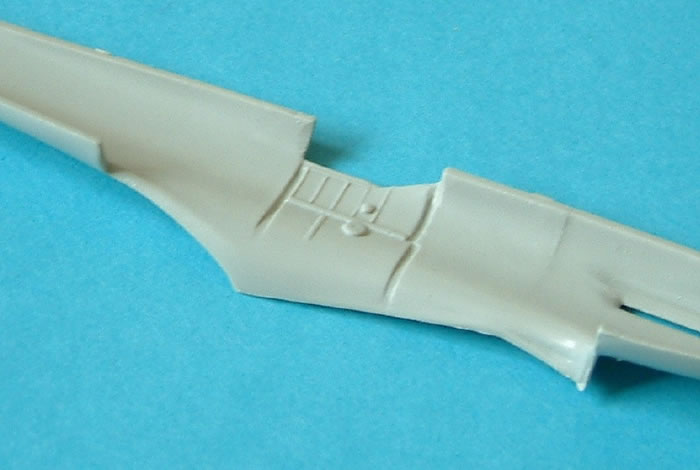
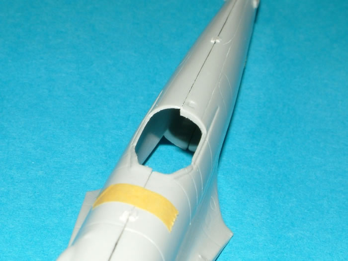
You can see from this picture how much material was removed.
Using the Hasegawa fuselage as a guide, the internal framing of the cockpit was built up using Evergreen micro-strip. Detail parts from the Hasegawa cockpit were used. The angled strip at the bottom replicates the abutment for the cockpit floor in the Hasegawa fuselage.
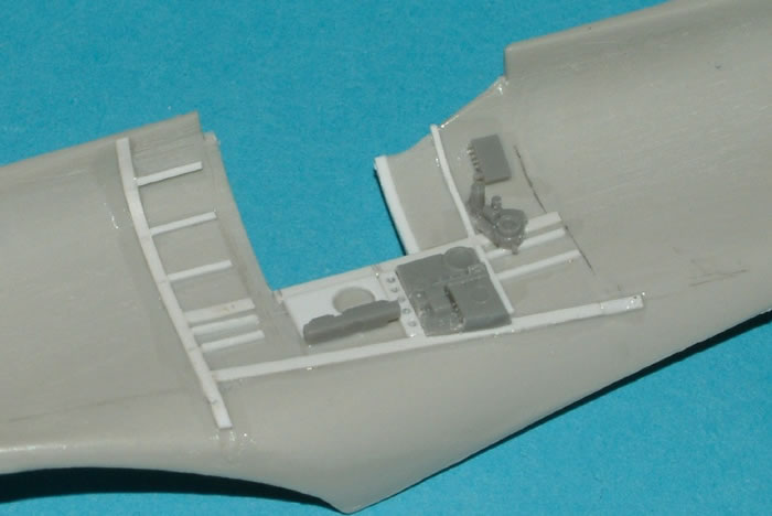
The rear of the cockpit opening was notched to take the top of the Hasegawa bulkhead and allow it to sit flush with the rear of the cockpit door opening.
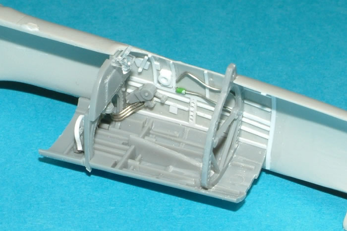
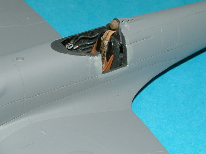
The same technique was used for the other side of the cockpit. Here you can see the Hasegawa parts fitting very neatly into the Aeroclub fuselage. I did have to relocate the rear bulkhead aft by a millimetre or two, as there is a difference in the dimensions of the two cockpit apertures. Telephone wire (the type used inside your house) was trimmed and bent to replicate some of the ‘plumbing’.
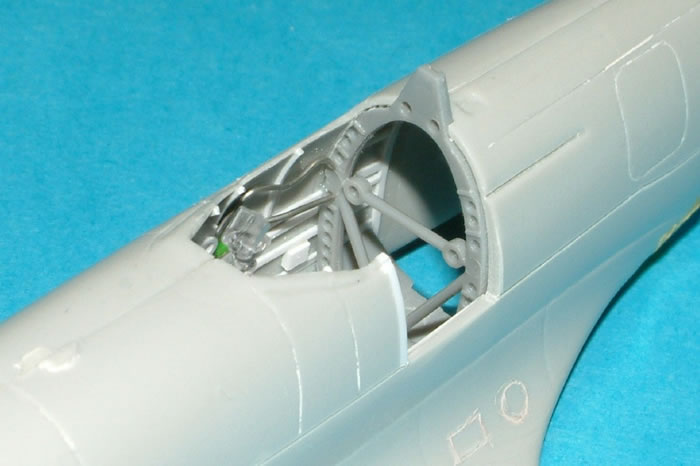
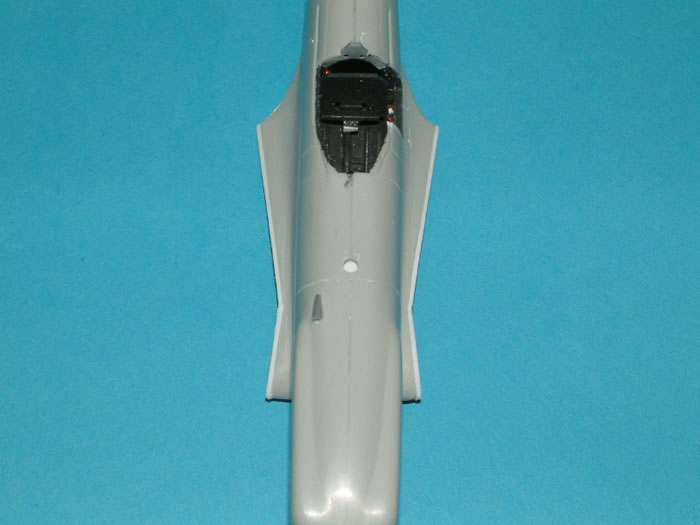
Here you can see how the Hasegawa frame sits in the fuselage. This is a dry fit and, once the fuselage halves were properly joined, the aft bulkhead aligned nicely with the rear of the cockpit door opening.
Unfortunately, I had removed the cockpit door from the fuselage before realising that the Ultracast replacement (intended for the ICM kit) was slightly smaller! (Measure twice - cut once). Using a section of Micro-strip, the width of the cockpit door opening was reduced to match.
The fuselage mouldings were also thinned where the rudder was to attach.
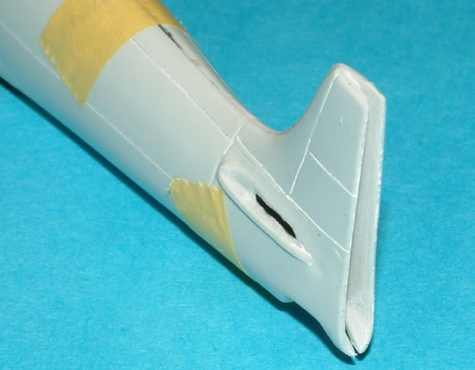
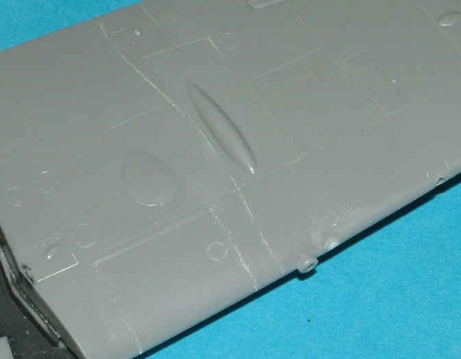
The engine cover bulges have an odd shape to the front of them (as do the Airfix F22/24 and Seafire 46/47) but these were easily corrected with Milliput. The exhaust cut-outs were backed with plastic card to accept the Hasegawa examples.
The next stage was to modify the Hasegawa wing to a Seafire F17 configuration. As is usually the case, a response to a question on HyperScale informed me that the wing-fold is identical to that on the Seafire III and a scan of a wing plan was also supplied. This plan was exceptionally helpful in modifying the panel layout. I used the wing from the Airwaves Seafire III conversion as a template to make a scribing guide from sheet styrene.
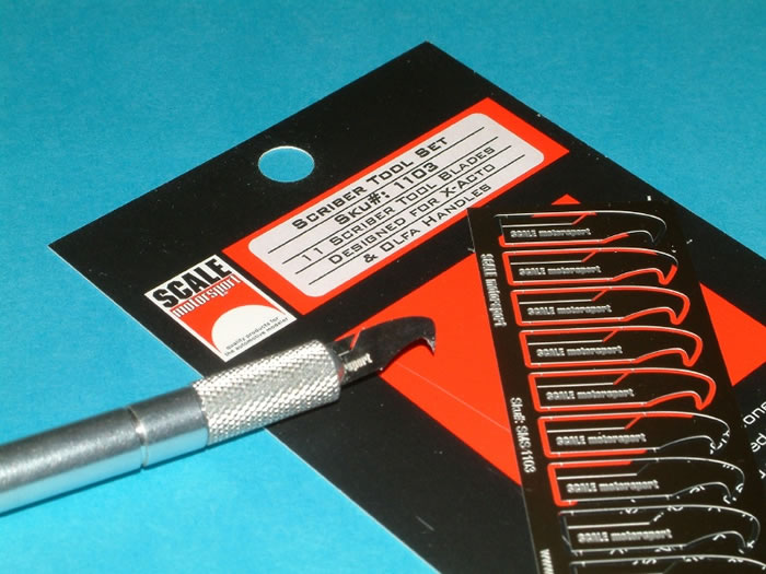
I used a scribing tool made by Scale Motorsport. I believe this is intended for die cast cars. It is only 0.2mm thick and works well on plastic in this type of application. It is available from Grand Prix Models in the UK. There are eleven blades in each pack.
This was also used to sharpen up the panel lines on the fuselage and to scribe the other alterations to the wings. It is here that I noticed a difference in this particular Aeroclub kit. The plastic, compared to the F21s that I have used, has a surface almost as though it has been glazed; and is in many ways like a varnish coat. When scribed, the hard surface flaked off in places leaving a ragged edge which needed a fair amount of sanding to rectify.
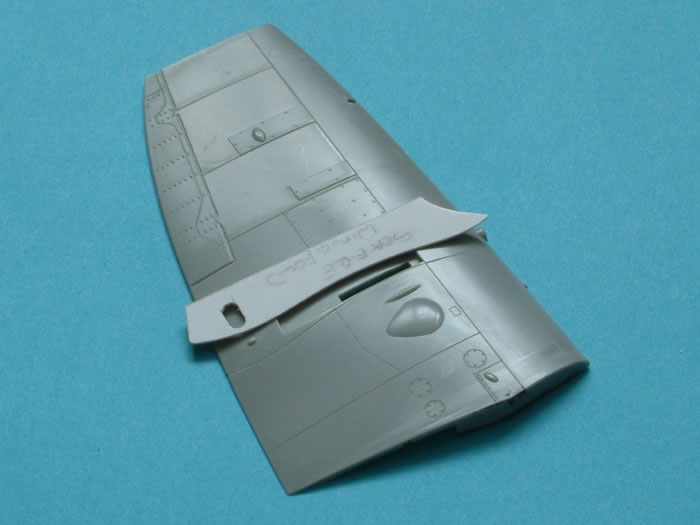
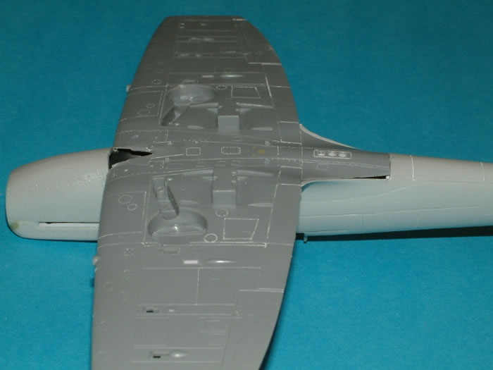
The redundant cartridge chutes were filled on the underside of the Hasegawa wing, the wing fold line and revised panelling were scribed in. The original signalling lamp was filled with Milliput and apertures for the three colour signalling lamps added. The outboard profile of the wheel wells was modified to suit the wing-fold break.
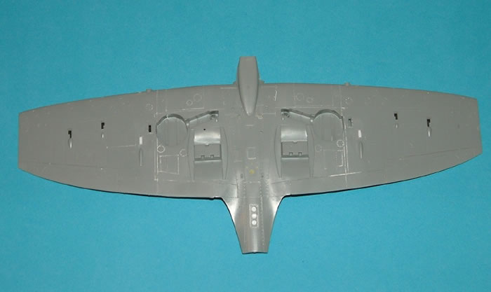
After the upper and lower wings were joined the outboard cannon locations were filled with plastic rod and smoothed off. The leading edge fuel tanks were scribed in.
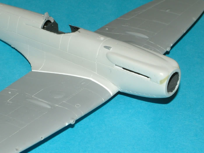
There is an air intake on the engine cowling which is represented on the fuselage but I chose to sand this smooth and replace it with a scratch-built one.
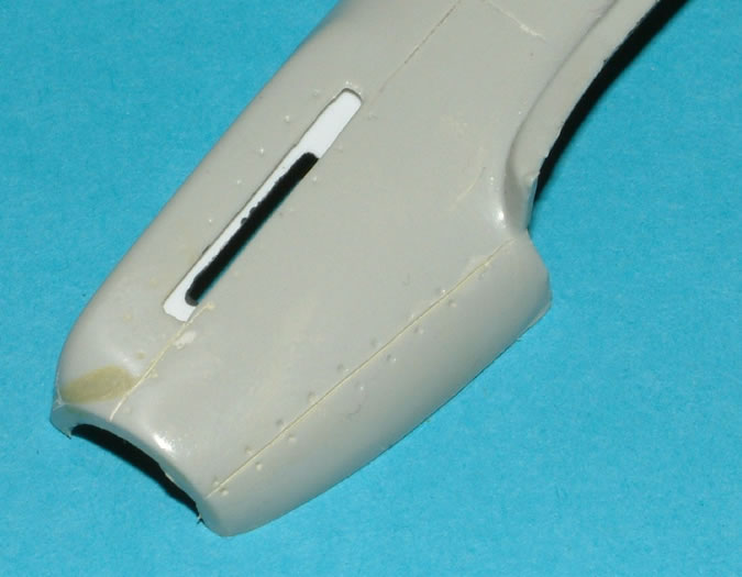
The fuselage halves were joined together. I had already decided to restrict the wing root alterations to the fuselage and create a match for the Hasegawa wings. This was done by filing back the mouldings to create surfaces parallel to, and 0.04 inches (approx. 1 mm) from, the wing surface. Then plastic strips were attached ready to be shaped to suit the wing profile without having to touch the root area of the wings in any way.
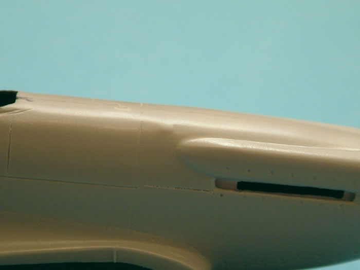
Here is the fuselage with the strips glued in place. This picture also shows the air scoop and the fuel filler aperture.
Prior to working on the fuselage wing root it was important to ensure that the underside of the wing aligned well at the aft joint of the wing to the fuselage. The inner edge of the fuselage was reshaped to allow the trailing edge of the wing to sit on a ledge created by laminating strips of thin plastic card across the inside of the fuselage. After a lot of filing, scraping and trial fitting it looked like this.
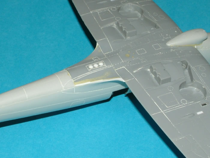
Aeroclub does state in their instructions that using the Hasegawa wing will require some work to make this area fit well. I filed, scraped and sanded the fuselage wing root curvature to remove the step at the joint to the wing (possibly due to the Hasegawa wing being thinner than the other two options). The mating faces were also adjusted to maintain the correct dihedral. Initially, the Hasegawa carburettor intake was fitted to the lower wing. This was then partially removed to leave its base fixed in the wing to accept the correct Aeroclub version.
This is the finished wing root joint.
Once the wings were glued in place the gaps in the aft edge of the wing root fillet were partially filled by inserting strips of plastic card and roughly sanded. Milliput was added to fill the final gaps before finally smoothing off. Lost panel lines were re-scribed. This is the result with the Aeroclub carburettor intake in place.
Paintin, Markings and Finishing Touches |
Under a coat of Halfords' Grey Primer (an aerosol can product intended for car repairs) it looked liked this.
The seat is Ultracast’s ‘Late Spitfire with Q Harness’ resin part. I removed the top sections of the harness and replaced them with plastic strip to take them through the armour. The armour support was made from plastic card. David Brown’s book “The Seafire” includes a photograph of this particular aircraft in flight and I believe that there is a headrest visible.
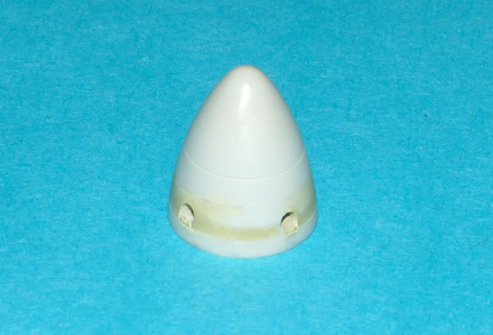
Unusually, the Aeroclub spinner, when fitted to the propeller back-plate, had a distinct change in taper across the join. The parts were glued together, the joint area filled with Milliput and reshaped. The additional join line was added with a sewing needle held in a tool clamp and then, with both on a plate glass sheet, the spinner was turned against the needle until the required groove depth was obtained.
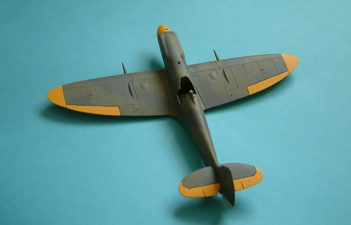
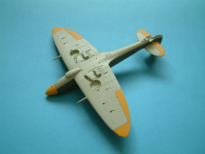
Here is the completed airframe, prior to gloss varnishing. I used the Hasegawa tail-plane; this required a little reshaping of the joint but, on reflection, the Aeroclub part is as good and would have fitted with less work. Phoenix Precision Paints (Extra Dark Sea Grey, Dark Slate Grey, Trainer Yellow and Sky) were applied with Sable paintbrushes. Humbrol paints were used for the interior.
The rest of the build was completed with the Hasegawa undercarriage and tail-wheel. I used Ultracast’s 4 spoke, block treaded tyre, main-wheels. The arrester hook came from the Airfix FR 47. Aerials were snipped from guitar strings.
Varnishes used were Ronseal ‘Hardglaze’ Polyurethane gloss (thinned with 75% White Spirit). After the decals were applied, Ronseal Polyurethane ‘Mattcoat’ was used straight from the tin. I’ve been using these varnishes for years and they show no signs of discolouring, even over white. Careful cleaning of the brushes after use is essential!
I understand that spraying polyurethane based products can be hazardous.
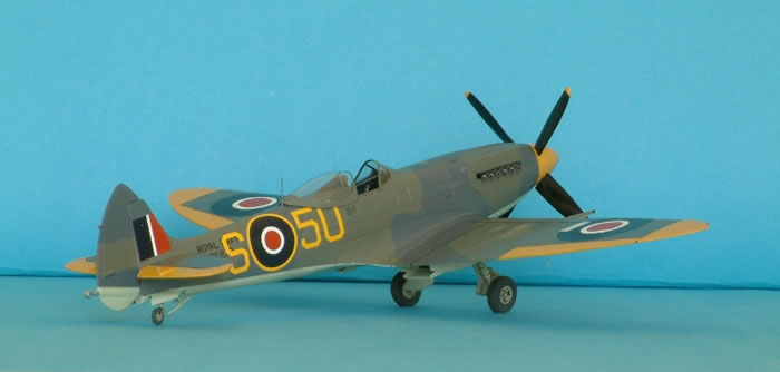
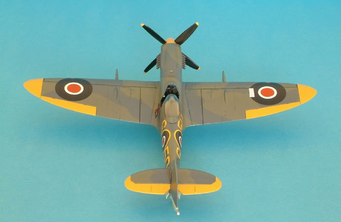
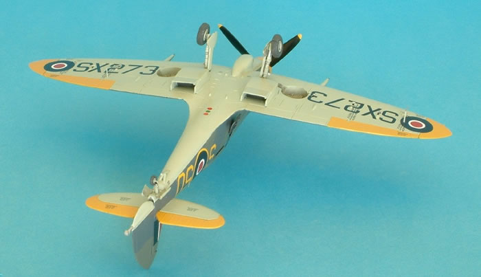
The aircraft is finished as Seafire Mk17 SX273 (S-50) from 741 Squadron, Operational Flying Training Unit, Air Warfare School, RNAS St. Merryn (Cornwall) 1947.
Decals are from Aeromaster Sheet 48-697 “Super Seafires 1 (Griffon Powered Part 1)”.
Thank you to Aeroclub for producing these conversions. The end results are always well worth the effort.
Model, Images and Text Copyright ©
2009 by Ken Stanton
Page Created 22 July, 2009
Last Updated
22 July, 2009
Back to
HyperScale Main Page

|
 Home
| What's New | Features | Gallery | Reviews | Reference | Resource Guides | Forum |
Home
| What's New | Features | Gallery | Reviews | Reference | Resource Guides | Forum |