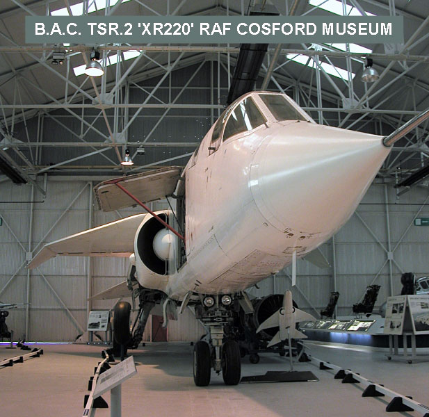
Airfix 1/48 scale TSR.2 Technical Note
Main Gear Angle
by Steve Naylor

HyperScale is proudly supported by Squadron
Following the posting on Hyperscale (13 February 2009) of his article on correcting the gear leg angle on Airfix's new 1:48 TSR.2 kit, the author monitored several threads online, debating the true gear leg angle on the TSR.2. Given the likelihood that aftermarket manufacturers, as well as fellow modellers, may well be using his article in a commercial venture, the author began to feel that, despite the caveats given in the article regarding the basis of his argument, that it was incumbent on him to attempt to ascertain the true angle as soon as possible. The resulting visit to the RAF Cosford Museum is described below, but the conclusion reached is that the gear leg angle on the TSR.2, is actually 18 degrees outwards from vertical plane.
Back on 13 February 2009, my article on correcting the splay of the main gear leg angle on Airfix's new 1:48 TSR.2 kit (see http://www.hyperscale.com/2009/features/tsr2splaysn_1.htm), appeared on Hyperscale, along with Brett's kit review and reference video of the two surviving airframes. The background as to why I felt that the kit's angle was wrong and the basis for my correction are outlined in the article, so I will not go over that again. However, in the aftermath of its appearance online, I saw some discussion of the merits of the correction, as well as disagreement with the angle I used (15 degrees) and debate about the gear leg's actual angle plus suggestions for the 'correct' one.
Discussions in these forums (particularly on 'Hyperscale' and 'Britmodeller') seemed to coalesce around two figures; a) that the angle is actually 18 degrees (Damien Burke, from good photographs taken by him of Duxford's XR222 - see the 'Thunder & Lightnings' website at; http://www.thunder-and-lightnings.co.uk/tsr2/walkaround.php), and b) Martin Hale on the Britmodeller TSR.2 Kit forum, who apparently got to speak to Airfix's Trevor Snowdon recently at Yeovilton (Model Show?), who apparently stated that Airfix used 21 degrees, based on 'production drawings'.
Examining Damien's photographs, the angle certainly looks like 18 degrees and equally, could not be 21 degrees, albeit that the most useful photographs are 'head-on' to the aircraft's nose, rather than taken directly in front of the main gear legs. The assertion attributed to Trevor Snowdon is interesting for two reasons; firstly because it alludes to the existence of production drawings (when it was widely thought that none had survived) and secondly, it seems to suggest therefore, that despite having access to museum examples, this feature was therefore not physically checked on either survivor. This latter point is obviously an extrapolation on my part however.
In an ideal world, I would have physically ascertained the true gear leg angle before my original article had been posted, but time was pressing, both for the article (to coincide with Brett's kit review) and my own kit build. Equally, at the time, I certainly could not justify the time or expense of visiting either survivor (at Cosford or Duxford) from my location, just to check this one aspect. Fortunately, an opportunity arose to combine a long weekend break with friends in Wales (relatively, not that far from the RAF Museum), with a visit to Cosford to examine TSR.2 XR220. As a result, I duly visited the RAF Museum at Cosford on 2 March 2009, prepared and equipped for the task, but dependant on the access available.
Direct measurement, is obviously the most accurate way to record the main gear leg angle, dependant on both physical and practical access. Direct angular measurement is not really possible though, given that the TSR.2's gear leg is angled both outwards and rearwards, i.e. at a compound angle. Using a plumb line and tape measure however, it would technically be possible to 'drop' key dimensions from both gear legs to the floor and then (knowing the height from the floor to these datum points) calculate the true angle.
Unfortunately, whilst XR220 was the most practical example for me to get to, it proved not to be an ideal candidate for survey. Not only was the aircraft displayed with the bomb bay doors hanging down in the open position, but also had the airbrakes out and the Starboard main gearbay doors open (a feature not normally open when on the ground)! This had the effect of making it impossible to measure directly across from the top of one gear leg to the other, though this dimension could have been indirectly measured as stated in the paragraph above. As you might suspect, all this is also a bit of a health and safety nightmare from a museum's point of view, so it was a case of 'reverting to Plan B'.
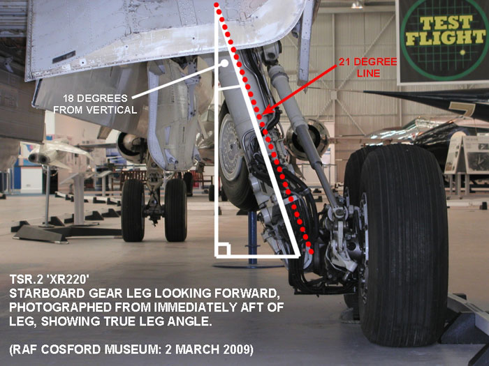
My only remaining option therefore, was to visually assess the leg angle, by setting up a levelled survey table (an adaptation I have made to my camera tripod) immediately to the rear of the mid-point of the Starboard undercarriage leg (a position derived from the reference drawings). From this platform, I then made repeated measurements of the leg angle by eye, using a large draughtsman's adjustable set square.
The readings taken were all fairly consistent (+/- 0.5 degree) and from them it is possible to say with some certainty, that the undercarriage leg on the TSR.2 (at Cosford anyway) is indeed 18 degrees outwards from vertical plane. As a double-check, I also deliberately set my adjustable set square to the 21 degrees attributed to Airfix, an angle close to that I achieved when dry-fitting the kit's components, which showed that this is definitely not the true angle.
The result of this assessment is shown in the photograph below, taken with the camera sat in the same position on the survey board, from which the angle assessment was made.
-
Naturally, the above result is technically only true of the Starboard gear leg on XR220. Were it not for the proximity of an engine exhibit and other clutter, I would have repeated the exercise on the Port gear leg to be absolutely sure.
-
There has been some debate as to whether any angular disparity between TSR.2 gear legs and their drawings, might be due to the main gear legs having a degree of flexing (other than the natural flexing inherent in any material), as part of the design to accommodate rough field landing/take-offs. Having taken a closer look at XR220's arrangement, I can say that the top of the gear leg is of one-piece (the top of the shaft of the main leg, plus the inner and outer lateral support struts), with a pivot shaft passing laterally right through this upper feature, pivoting on trunnion bearings fitted to the inner and outer walls of the wheel well. This means that the gear legs themselves do not flex laterally, so unless the prototypes were at some point fitted with gear legs manufactured to different angles (not impossible, but much of the associated mechanisms would have needed alteration as well), then this seems not to be a factor.
-
The only other factor which can affect both the perceived and measured gear leg angle, is the 'sit' of the aircraft. This would normally come down to weight distribution (fuel load balance or ordnance fitted), the state of oleo hydraulics or asymmetric tyre pressure differences. As an exhibition aircraft, XR220 presumably contains no fuel(!), is not fitted with any ordnance (real or dummy) and her main gear oleos (unlike XR222 at Duxford) are completely compressed. So barring any slight disparity due to uneven tyre pressures on one side of the aircraft (and there was no obvious sign of this), I think the result I have observed still holds true.
Model,
Text Copyright © 2009 by Steve Naylor
Page Created 27 March, 2009
Last Updated
27 March, 2009
Back to HyperScale
Main Page |
 Home
| What's New |
Features |
Gallery |
Reviews |
Reference |
Forum |
Search
Home
| What's New |
Features |
Gallery |
Reviews |
Reference |
Forum |
Search