|
Hawk + Heller + Italeri 1/72 scale
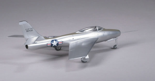
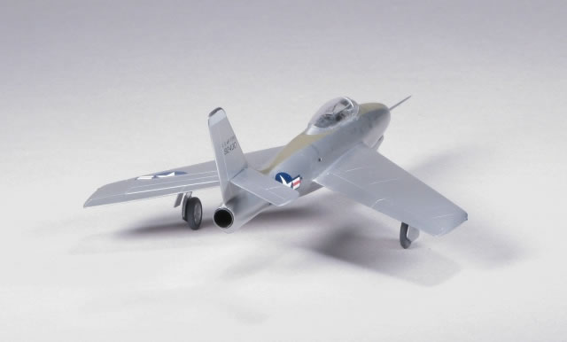
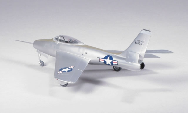
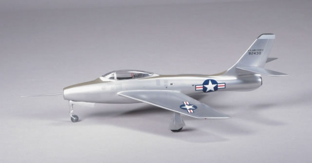
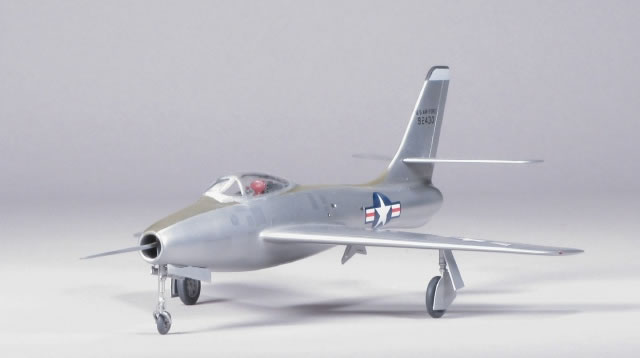
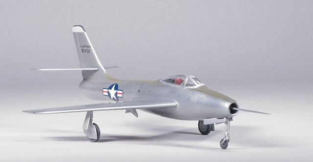
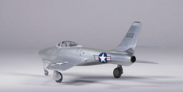
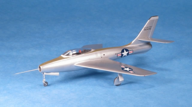
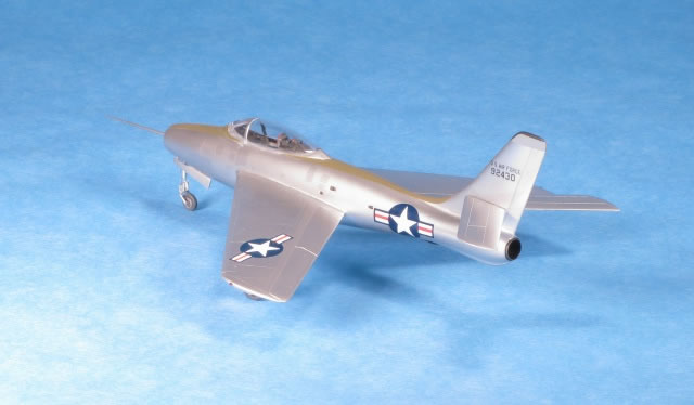
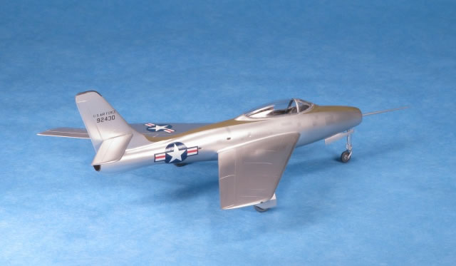
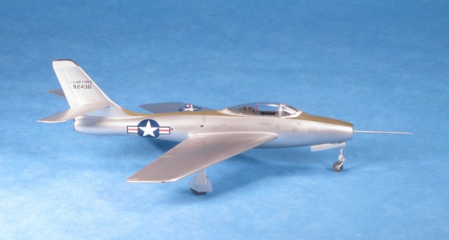
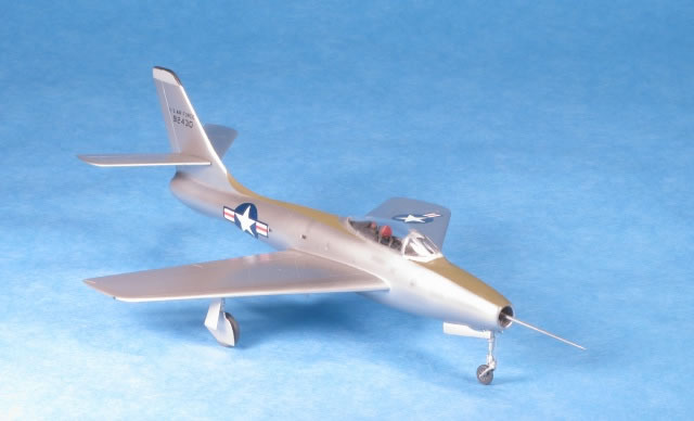
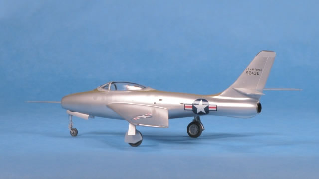
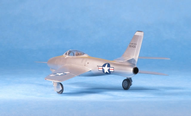
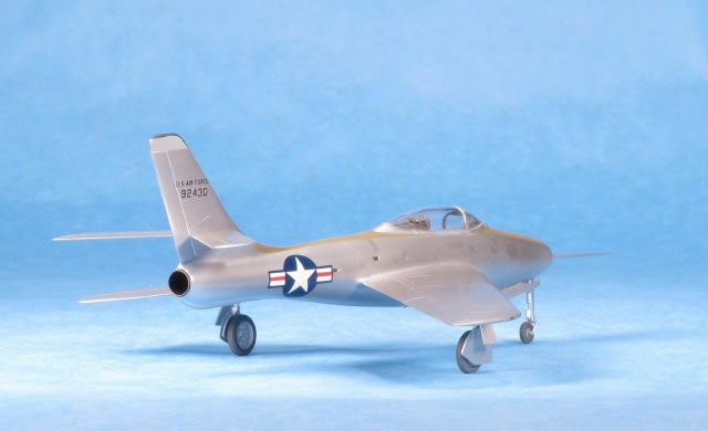
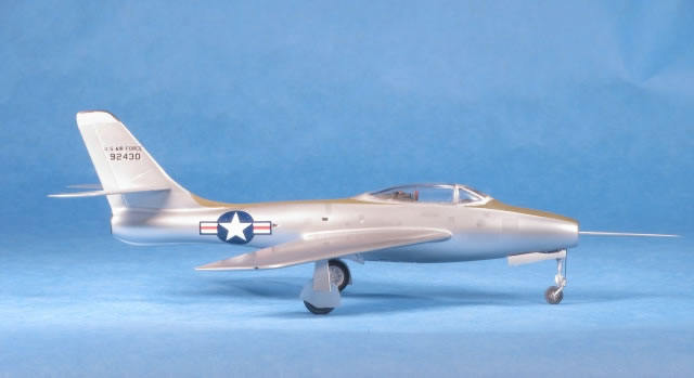
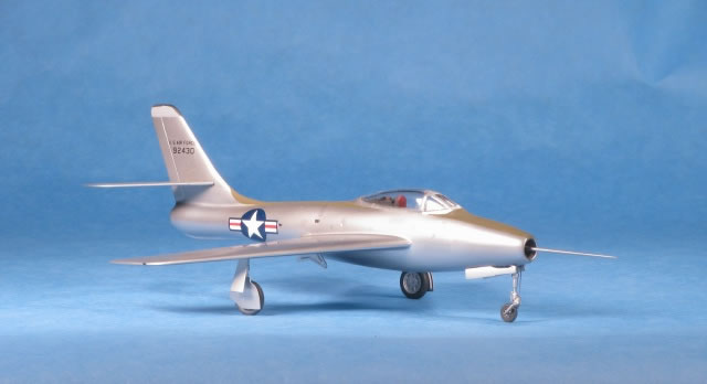
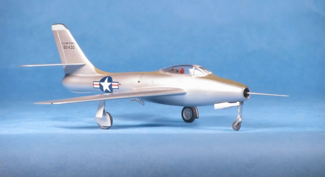
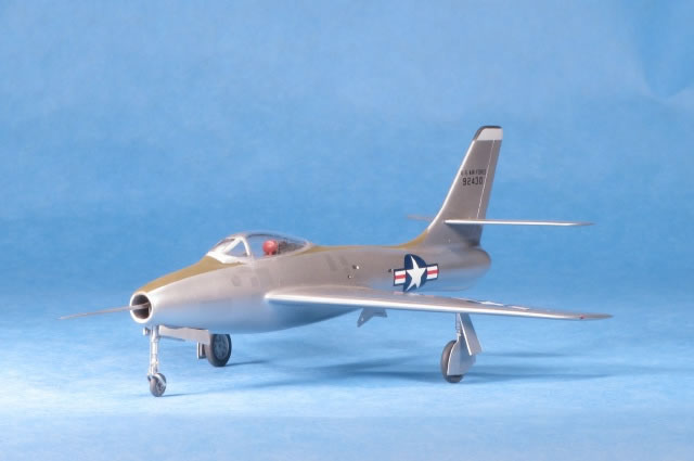
Republic YF-96A Thunderstreak Prototype
by Bill Dye
|
Republic YF-96A Thunderstreak Prototype |

HyperScale is proudly supported by Squadron.com
I built the 1/72 scale Italeri F-84F a long time ago and did it in green/gray camouflage; it never sat well with me. I guess I was used to shiny silver F-84Fs but after dealing with ‘Liqui-Plate’ I caved and went with the camouflage. Recently, well a few years ago, I completed the vac kit of the Thunderscreech (Hyperscale article) and a year or so later the XP-84 Thunderjet prototype (also a Hyperscale article) which required shortening the Heller kit F-84E fuselage.
I seemed to be on a Republic prototype roll so I just had to do the next logical model and that was the prototype for the F-84F, the YF-96A. This prototype was basically an F-84E fuselage fitted with swept wings and tail surfaces and a ‘V’ shaped windscreen. How hard could it be?
History
The Republic YF-96A (S/N 49-2430) was the early and brief designation for what evolved into the F-84F. The aircraft was the first swept wing version of the Thunder family and was built by taking an F-84E fuselage and adding a sweptback wing and tail assembly. The aircraft's first flight was on 3 June, 1950 with Republic test pilot Oscar P. “Bud” Haas at the controls. The YF-96A was powered by the Allison J35. Two additional prototypes were built as XF-84Fs (S/N 51-1344 and 51-1345). These aircraft had a 7" section spliced into the fuselage to make room for the larger Wright J65 (Sapphire) turbojet which also required a larger volume of intake air. This variant was then named the YF-84F mostly to ease funding from congress by selling a 55% parts commonality with the straight winged Thunderjets. Although later it was found to be more like 15%. Many phases of testing were conducted until the F-84F production began in November 19521.
The YF-96A (S/N 49-2430) was later modified to test the feasibility of bomber aircraft carrying their own escort fighters in the bomb bay. The FICON (FIghter CONveyor) project never passed beyond the test phase because in-flight refueling proved more practical and efficient for long-range escort of bomber aircraft.
.
The Kits and The Plan
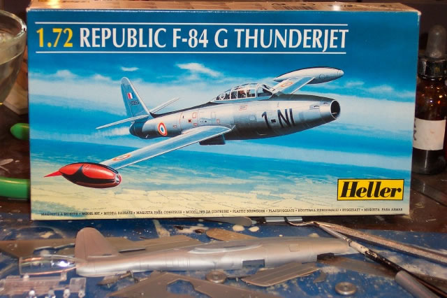
I studied my references and came up with a plan. It looked like I could take a Heller F-84E fuselage and graft on the flying surfaces from an Italeri F-84F kit. But what about the V shaped windscreen? I resigned myself to having to make a master and vac a new canopy/windscreen . .sigh.
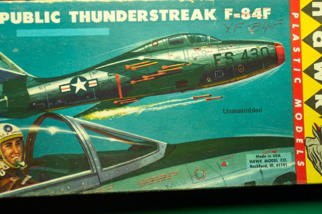
I actually started this project and got to the point where it looked like an airplane – still dreading the canopy situation. But then I found an old HAWK kit of the F-84F, as they called it, on e-bay. I bought it and the shipping charges were actually less than the cost of my house. After looking at that kit and the references I realized that it was actually the YF-96A; who knew? It had a bubble canopy with a ‘V’ shaped windscreen; just what I needed.
So the project evolved into a Heller E/G fuselage, Italeri flying surfaces and the HAWK top fuselage cockpit area and canopy. The HAWK kit resembles, quite accurately I believe the YF-96A; at least from the photos I studied. If I were to do it again, I might consider starting with the HAWK fuselage and adding the Italeri flying surfaces. That said, the problem with the HAWK kit is that there is no cockpit, just a slab with a guy’s head stuck to the slab and no landing gear wells at all. Second thought . . .maybe my approach wasn’t so bad after all. Either way was work. Of course now that I’ve done this, Anigrand or someone will undoubtedly come out with a resin or injection model.
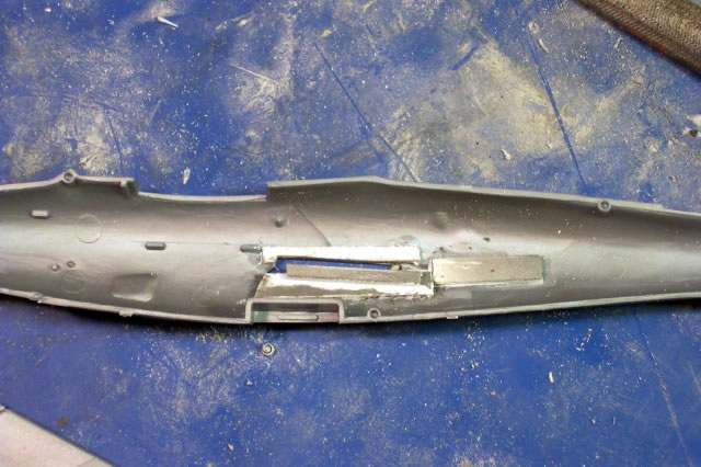
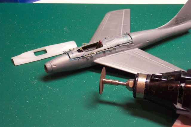
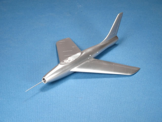
The first step was to see if this concept of grafting on Italeri swept wings to the Heller fuselage would even work. With an evening of looking at reference photos and drawings, some measuring, cutting, re-measuring, re-cutting, the wing joint was roughed in. It wasn’t that hard. Really. It was simply removing the straight wing root fillets from the F-84E fuselage and then finding the location of the swept wing root chord leading edge and making a new slot for the wing tab; just some thick plastic strips glued to the inside of the fuselage. How hard is that?
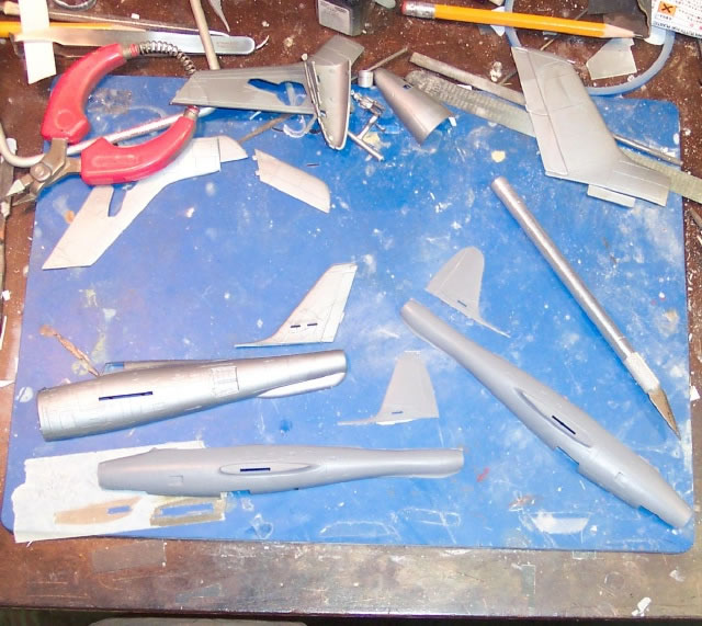
Look at it this way: Heller and Italeri kits combined, maybe $20 max at a vendor table, if that. That’s two drinks at the airport. Pick up the file, take a deep breath, and file away the root fillets.
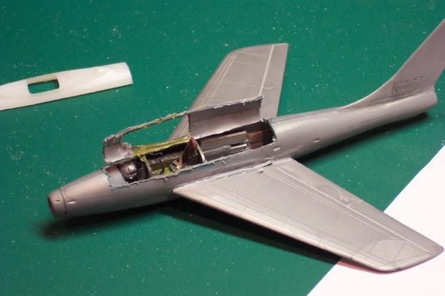
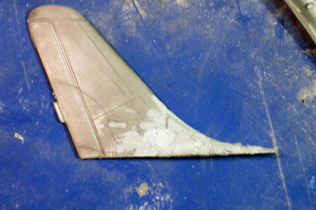
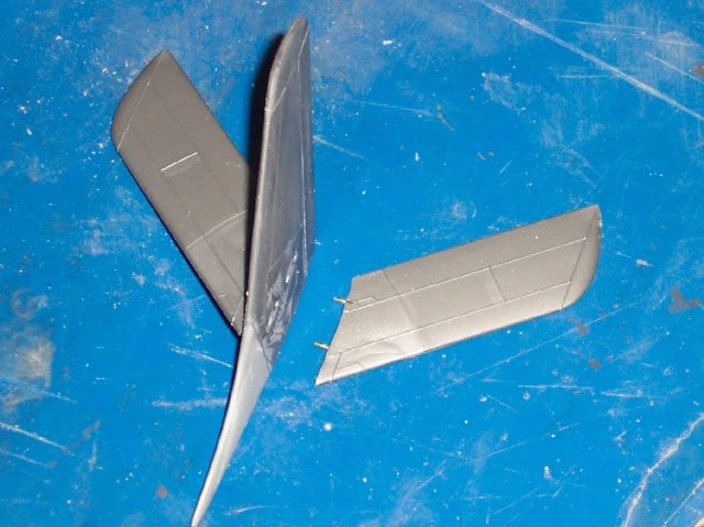
Next were the aft flying surfaces. The Italeri F-84F tail had to be spliced onto the Heller ‘E’ fuselage but with a slightly greater sweepback angle (just a few degrees) than the ‘stock’ F-84F (at least based on comparing photos and drawings of the YF-96A to the production F-84F). So I cut off the vertical tails; one off of the Heller fuselage (toss that one) and the swept tail off of the Italeri F-84F kit. Next a new transition piece, the lower curved part between the top of the fuselage and the leading edge of the vertical tail, was made out of scrap plastic. Putty did the rest. Note that it’s easier to align the tail sweepback angle while the fuselage halves are still apart. That way the fuselage half can be laid flat on the work surface making the vertical tail integration measurements, alignment, cutting and fit checks much easier.
The horizontal stabilizer root chords were sanded to match the vertical tail interface. Small brass rods were used as mini-spars and locating pins for gluing the all of these surfaces to the fuselage.
After I was convinced that the concept would work, I built up the cockpit using the kit parts with no special fanfare since this was going to be a closed canopy model. I wanted to admire the lines of the airplane (cockpit enthusiasts would dress this up considerably). I did the old ‘white paint on instrument panel followed by interior black then scrape away the black to make white dials’ trick.
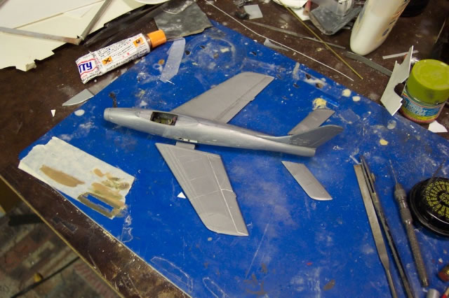
Weight was added, the cockpit was installed and the fuselage halves were joined. Next I attached the vertical tail, strengthening the joint with brass pins, followed by installing the Italeri wings.
The use of a flat ‘self-healing’ matt with rectangular grid lines and some drafting triangles aided the alignment. Since there were new wing slots, all degrees of freedom had to be accounted for and aligned. This took about half an hour.
The wings were tacked with a drop or two of super glue then, later, Tamiya Liquid Cement. The horizontals were all flying tails so those could be painted and then installed at the end of the build.
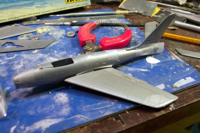
But wait . . . it was here I received the HAWK kit in the mail. There was the V shaped canopy but the V shaped canopy frame was part of the HAWK kit fuselage. I looked at the Heller fuselage with Italeri wings that I had just built up and looked at the HAWK kit fuselage, my fuselage, HAWK fuselage; “Hmmmm, should I do this?” I broke out the micrometer and determined that the fuselage width dimensions were very close to one another. So, the answer was: Yes.
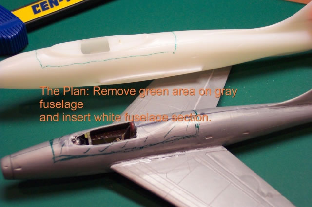
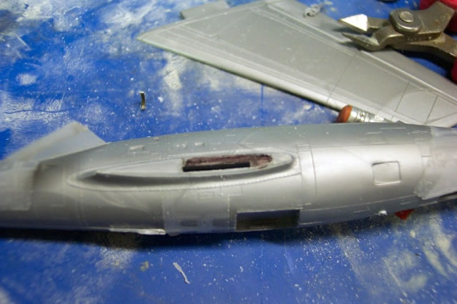
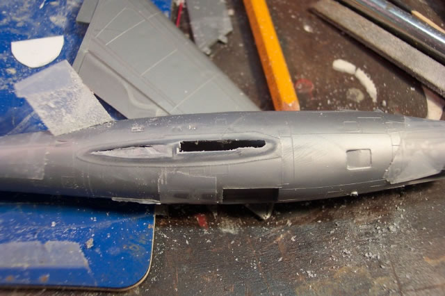
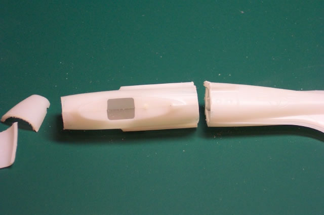
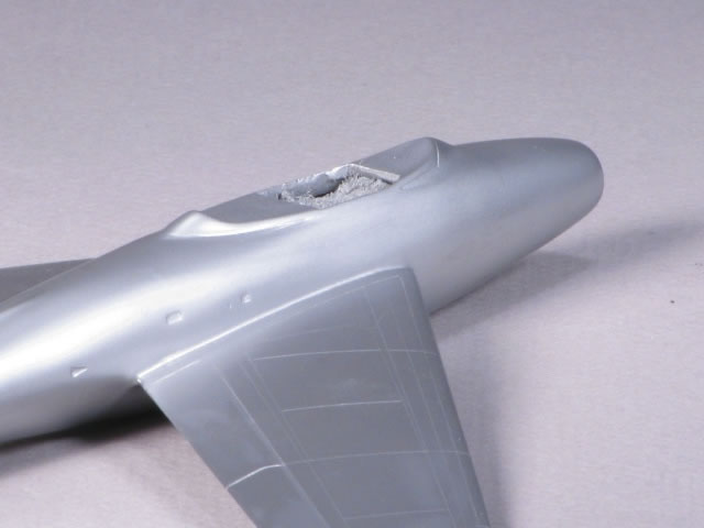
I took out the trusty Dremel tool and cut off the top of the fuselage around the canopy; I know, crazy, but it’s just plastic. I made the ‘incision’ such that it did not destroy my super detailed cockpit (note sarcasm).
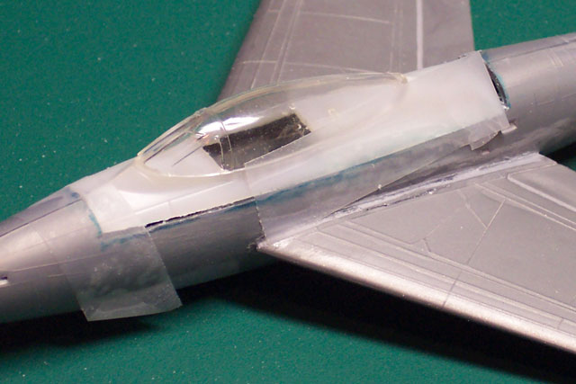
I glued together the HAWK kit fuselage halves and let that dry overnight. Then, I cut out the top portion of the HAWK fuselage that included the V shaped canopy frame to match the part I removed from the Heller fuselage. With some filing, examine, file some more approach, the HAWK canopy fuselage section was integrated with the Heller fuselage – not a bad fit actually – with just a few small shims and some putty. Although major surgery, with a few measurements it was pretty easy. Sometimes the surgery just looks bad, but with some putty and sanding it comes out alright. In this case the patient lived. Admittedly Dr. Dye sighed with relief after that one.
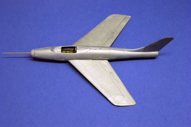
The pitot probe is a spun brass rod (Dremel tool, wear goggles).
[The secret to spinning the brass rod is to carefully hold the Dremel tool such that the rod lies on an indentation made on a flat surface – like a small slot carved into the edge of a piece of Pressboard (like my workbench top). Pressure and a filing motion can then be done with a file while the slot provides support for the rod (while it’s spinning). You will see a great deal more brass come off more quickly this way! WEAR EYE PROTECTION! And don’t drop it into your thigh! Remember, you’re holding a heavy ICE PICK!]
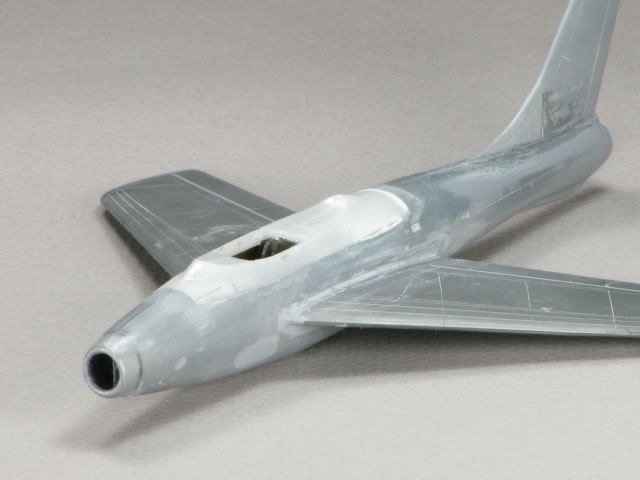
The raised panel lines were sanded off and I re-scribed the wings, the fuselage would be busied up with access panels.
Paint
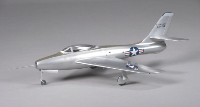
 The model was polished with the Micro Surface Polishing System (from Micro-Mark, worked great by the way). It took about an hour to go through all of the paper grits and the final polish to get the model smooth. The model was polished with the Micro Surface Polishing System (from Micro-Mark, worked great by the way). It took about an hour to go through all of the paper grits and the final polish to get the model smooth.
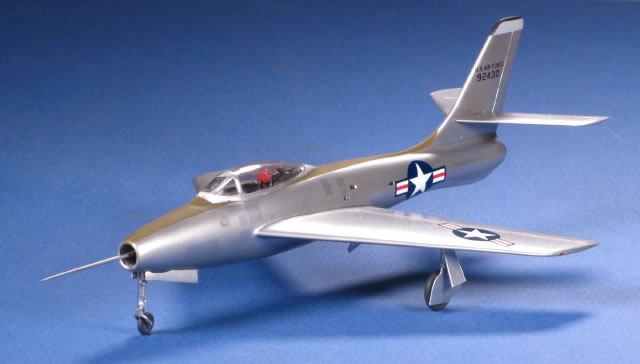
To get the myriad of access doors on the fuselage I first airbrushed the fuselage with some SnJ plus a few drops of Model Master Metalizer Dark Anodic Gray. After dry I cut out small rectangular and circular pieces of Tamiya masking tape using either a template or freehand and applied these to the model per the references. I re-sprayed over these and the entire airplane with pure aluminum SnJ. When I pulled the tape off there were the darker shade access panels.
The secret to SnJ is four or five mist coats spaced 10 to 15 minutes apart (as in . . follow the directions) and keep the paint agitated so the metallic pigment stays suspended while spraying. After the last coat I wait about 45 minutes and then polish the model with the SnJ polishing powder and a very soft rag. Then let it dry rock hard overnight. The entire model is then washed thoroughly to remove excess powder and carefully pat dried. No black base coat required.
The photos showed very little natural metal skin panel color differences so only a few things were highlighted. Model Master Enamel olive drab anti-glare panels were masked and painted on as well as the light gray and black on the vertical tail tip. Masking with Tamiya tape was not a problem over the SnJ.
Decals were minimal; a couple of stars and bars and a U. S. Air Force from the scrap box but the serial number on the tail were made from individual numbers from letter/numbers decal sheets.
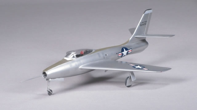
The main landing gears were from Italeri F-84F kit – close enough for the main gears – but a new nose gear was built up using brass and aluminum tubing and rod, and the Heller F-84E kit nose gear fork. Two new main gear doors were made from 0.010” plastic. Most of the doors were fitted with small brass wires for easier attachment to the fuselage.
The cockpit protective stuffing was removed, the seat was installed and the cockpit was thoroughly blown out with air from the airbrush. Then the canopy was polished and dunked in Future (actually that was done months earlier) and attached to the model with watchmakers watch crystal clear glue (Micro-Mark). Using Krystal Kleer would have worked well too (no glue strings as you get from the Watchmakers glue).
The canopy windscreen joint with the fuselage had to be smoothed after the model was painted. This was the difficult part. I did the best I could then masked, painted first black (interior color) then SnJ (exterior color).
The teeny weenie nav-lights were from Elf Productions and were given to me by Dave Hansen. The fuselage vents were washed with thinned black. The aluminum tube exhaust nozzle was painted with Model Master Metalizer exhaust, treated with some pastels and installed with just a press fit.
I know the process looks quite involved but, again, it’s just plastic. And plastic can be cut, puttied, filed and sanded until you get what you want. This was fun and I enjoy seeing this sitting next to the XP-84 and the ‘Screech’.
Now what can I do with the wings and tail from an Italeri RF-84F Thunderflash and a Heller F-84E fuselage? Next time.
Done. Bury me with sand paper.
References:
-
Keaveney, Kevin. Republic F-84 (Swept-wing Variants) Aerofax Minigraph 15. Aerofax, Inc. 1987; pp 1,2, 34
-
Davis, Larry, et al. F-84 Thunderjet in action, Aircraft Number 61, Squadron Signal Publications, 1983; p. 6
-
Johnsen, Fredrick A. “Thunder Maker, Pt. 1”, AIRPOWER, Vol. 6 No. 3. Sentry Books, Inc. May 1976; p. 30
Models, Text and Images Copyright © 2010 by Bill Dye
Page Created 9 May, 2010
Last Updated
9 May, 2010
Back to HyperScale
Main Page

|
 Home
| What's New |
Features |
Gallery |
Reviews |
Reference |
Forum |
Search
Home
| What's New |
Features |
Gallery |
Reviews |
Reference |
Forum |
Search