Czech Model 1/48 scale
Curtiss XP-55 Ascender
by Andrew Garcia
 |
Curtiss XP-55 Ascender |

Airfix's 1/72 scale Tiger Moth is available online from Squadron
Summary
Catalogue Number: Czech Model Kit No. 4806 - Curtiss XP-55 Ascender
Scale: 1/48
Contents and Media: 34 parts, a bag of about 19 resin parts and two vac-form canopies, the plastic parts in grey plastic; with no clear parts tree, no photo-etched fret or masking sheet. Markings for one aircraft (box erroneously indicates two aircraft) is provided.
Price: MSRP USD $29.95 when released. Now OOP.
Review Type: Build
Advantages: First XP-55 Ascender as an injection moulded kit in 1/48 scale (the Collect-Aire Resin kit is the other alternative); crisp and consistent recessed panel lines; good quality resin parts; includes clear vac-form canopy (with one spare); thin decals; effective use of multimedia.
Disadvantages: Rough but well done (nicely scribed details) plastic moulding (no alignment tabs), kit decals missing important parts such as “Curtiss Ascender logo”, USAAF Aircraft Identification Plate, important stencils and prop logos. Detail accuracy issues due to limited run moulding plastic omissions (kit is missing nose light, pitot tube, armament barrel openings, etc). See detailed discussion that follows.
Background
The XP-55 Ascender was one of several USAAF WWII era prototypes testing the pusher fighter concept. This configuration promised some advantages such a concentrated cone of fire using heavy armament on the centerline without the need for prop synchronization components, lower overall drag, and enhanced pilot visibility. The XP-55 put the tail surfaces in front of the engine, and used a “free floating maneuvering elevator” – which is not a canard layout at the front of the aircraft. The reference books do a good job explaining this often stated error from some folks who think this aircraft had a canard control surface – it does not although it is similar in appearance. The canard control is a small fixed wing at the nose area with its own movable control surfaces.
The XP-55 promised next generation aircraft performance. During engineering proposals to the U.S. A.A.F. , Curtiss “guaranteed” a high speed of 507 mph (American Secret Pusher Fighters of World War II pg. 65) with a weight of 5,325 lbs. (empty). Once the final design for the airframe and power plant availability were factored in the performance slipped to a “guaranteed” performance of 419 mph (ibid pg. 75). The final prototype weighed 6,354 lbs. (empty) with a high speed of 377.5 mph at 16,900 feet. The final assessment by the flight team was the plane did not meet the contractor’s guarantees and its performance did not compare favorably with contemporary fighters in production.
In the late 1990’s through early 2000’s Czech Model was a plastic aircraft kit collaboration between a limited release/short-run low pressure injection moulded kit manufacturer in the Czech Republic and Squadron Products in the USA. The subjects, at that time, were only in 1/48th scale, The chosen aircraft initially depicted unusual subjects, experimental or research aircraft, and later represented some standard production U.S. Navy aircraft that had been sought after by modelers but neglected such as the Czech Model 4814 F3D-2 Skyknight and Czech Model 4809 Beech T-34C Turbo Mentor USN.
Kit releases stopped for a several years and a few years ago the Czech Model 4819 Beech T-50 Sky King (2009) and 1/32nd scale (F-80C Shooting Star & T-33A Shooting Star) releases brought the product line back to life. In 2005 they released the XP-55 kit through a cooperative effort with Squadron Products.
Why did it take nine years for me to get to this kit? Due to a water meter replacement program I had to relocate portions of my modeling stash. Most of my modeling stash is kept in a climate controlled subterranean man cave. I chose a far corner of my basement for its cool, dry and unused space years ago to place the prolific output of model kit manufacturers in preparation for future builds.
Recently a letter was received requesting access to the water meter in a replacement upgrade program. Doom and gloom was my initial impression at the thought of having to move my substantial stash to provide the contractor access. Despite all the work there was a reward far beyond getting a new meter. I had a chance to unearth some kits from long ago and redo my build schedule. Just before this event I read two books listed below as references. They were not available in 2005 when the XP-55 kit was released. One of the kits I found during the unexpected stash move was the Czech Model 4806 Curtiss XP-55 Ascender kit. This is a limited run kit and requires dry fitting, extra sanding accompanied by gap filling to get all of the parts to properly assemble. There are large ejector pin marks and stubs in places that require attention before assembly. The two new references provided a fantastic insight into the XP-55 and related aviation projects. The big bonus was both books had many clear photographs of all three prototypes and their airframe components. Rather than rehash more about the XP-55 and pusher aircraft history you should get those two books listed at the end of this build in the references section and have a good read. You will be motivated to build that old XP-55 model that’s waiting for you. Thanks to the superb reference books I now had a long list of changes and enhancements to the kit contents. Without these references I may not have built the kit due to its generally rough appearance.
The separate components of the kit (plastic, resin, decals, and instructions) are all bagged separately inside a less than sturdy cardboard box. The kit consists of two plastic sprues with 34 parts, a bag of 19 resin parts and two vac-u-form canopies, one being a spare. The resin is superbly cast and detailed, and once removed from their blocks adds improved detail to the model. The plastic parts are limited run with some rough areas requiring attention and clean up. Panel lines are very finely engraved and the sprue connections are of medium thickness making for an improved short run kit experience. During assembly I found the fit of the plastic to be good.
The four page instruction sheet is small but adequate. I had to use Hypersale’s forum for some assistance with the build step for parts # A3 and #A22. This was the only inadequate part of the instructions. The kit instructions for the 1/48th Curtiss XP-55 Ascender show in Step # 2, Fuselage Assembly, these two plastic parts near the tail but without any (to me) obvious placement or use. They go on the interior fuselage to box-in the top air scoop..... A22 is the base and A3 is the back. A3 rests against the rib on the interior right fuselage half in case you were wondering. Thanks to David C. Jones for his kind assistance. A small circle with an arrow by the manufacturer in Step # 2 for parts # A3 and #A22, would have fixed this concern.
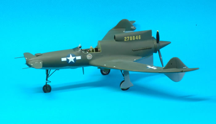
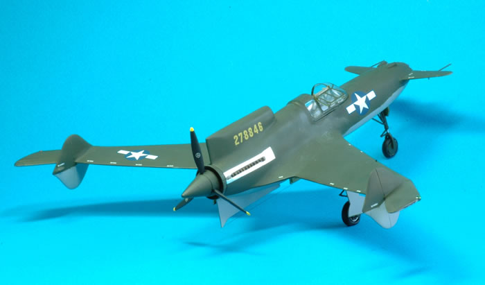
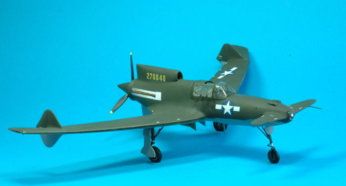
The box art sets an expectation that there are two decal options (“Decals for two versions”). The instructions and decal sheet are for one version which is the second prototype S/N 278846 and only existing airframe of the XP-55. Apparently the same serial number is given twice on the decal sheet. The kit provides the parts and decals for completing the second prototype near the end of its testing stage after being upgraded with various modifications. It was painted in the standard WWII olive drab topside over neutral grey underside scheme with yellow serial numbers. The decal sheet consists of the serial number and USAF insignia with a few “push, no push, no step, no handle” stencils, which are thin and in perfect register. No placement or use is given for the white stencils in the instructions
The wheel wells are not boxed in using plastic but are adequately done in resin despite overlooking a few hydraulic lines. The front landing gear doors are molded in one piece as part of the fuselage plastic which is an accurate representation of the actual aircraft which had the doors close after the gear locked in the down position. The first prototype, S/N 278845 had open landing gear doors with its landing light located on the nose gear. The landing light was re-located to the nose tip in S/N 278846 and S/N 278847.
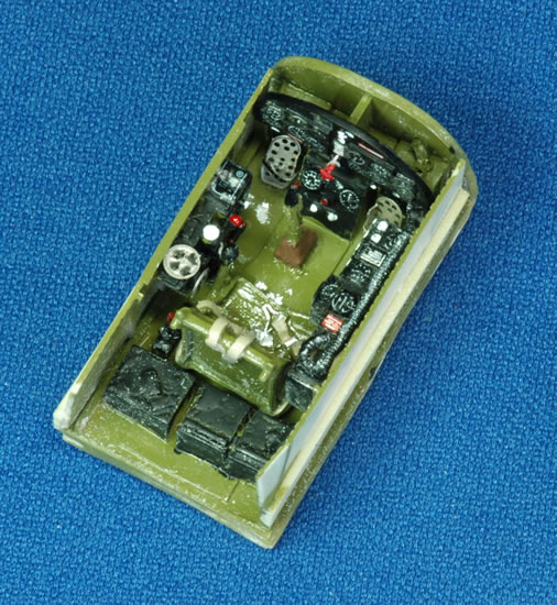
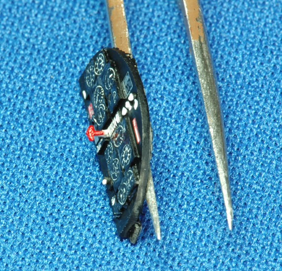
The resin parts look excellent and include additional detailing for areas such as the wheel wells and cockpit. In general it is a good effort because most of what you need for an acceptable OOB kit is included. The kit provides a cockpit composed of the resin seat with belts, instrument panel and sidewall details.
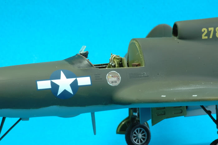
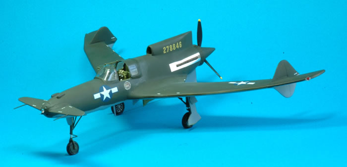
Weighted resin wheels are included along with a resin exhaust. The kit provides a vac-form canopy plus a spare which is a very useful provision. The canopy is very clear with subtle framework. I also acquired a True Details #41079 Fast Frames canopy detail which worked well. It provided a guide for cutting the canopy from its base. The canopy is one-piece, and I wanted an open canopy to display the additional cockpit detailing so some vac-form surgery was required to have an open cockpit.
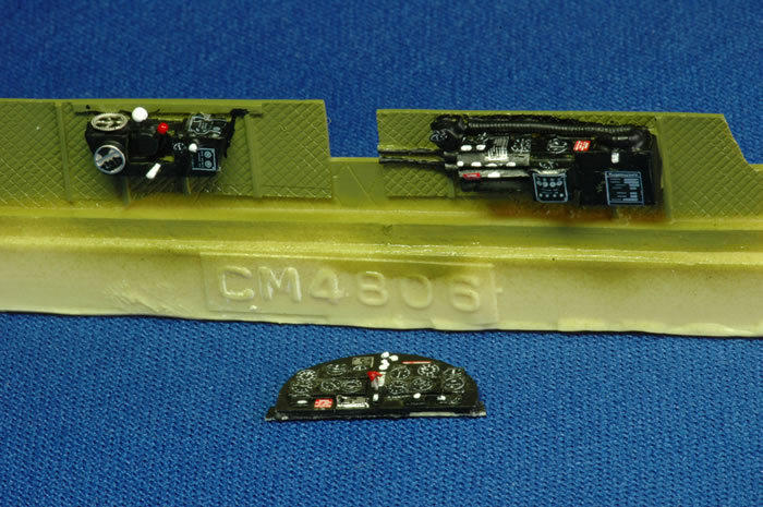
My initial impression of the resin cockpit was very favorable. The resin parts are very well cast.
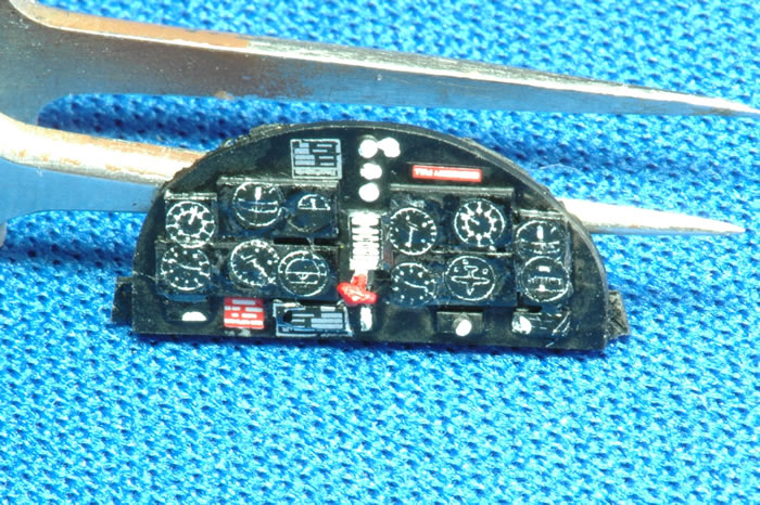
I was especially impressed with the resin wheels which are excellent. Once I stared at the actual cockpit photos and compared them to the resin parts some components were re-ranked to acceptable. Some added detail is required if it is to be an open cockpit model or if you like a cockpit resin to really mimic the actual physical cockpit to a high degree. A bit of silver dry brushing of the OOB bits along with some paint doesn’t make it in the case of an open cockpit but works for a closed canopy three-foot view build. The reason my opinion changed is the cockpit resin detail for panels, instruments, some “black boxes” are composed of a lot of small strips glued into the instrument dials and on most component areas so it looks fine, having some details, from three feet but to the naked eye at six inches it is not comparable to some of the Aires or other aftermarket cockpits – and not to the cockpit photos in the references. It was however an excellent starting point for detailing efforts.

I used a number of metal pins with cyano glue to join many components together due to the lack of locating tabs. In typical limited run kit engineering most large mating surfaces are butt joined. This required the mating surfaces to be prepared with some cleaning and sanding beforehand as well. Dry fitting prior to any assembly and on each sub assembly, particularly resin to plastic assemblies, to identify any shortcomings in the component fit is required. In general I was very pleased with the fit and did not find any fatal flaws.
The kit is designed to represent, based on the kit decals, the XP-55 S/N 278846 which was the second of three prototypes. I followed the kit instructions construction process and only had a problem with Step # 2, “Fuselage Assembly”. The two plastic parts A22 and A3 are shown near the tail in the diagram but without any (to me) obvious placement or use. They go in the interior of the fuselage to box in the top air scoop..... A22 is the base and A3 is the back plate.
At this stage I prepared a list of changes and enhancements based on my observations from reading the two reference books. It was very enjoyable to study the many detail photographs provided in these fine books and identify areas for improvement. The following recommended modifications are in no particular order and were the enhancements I added to this build.
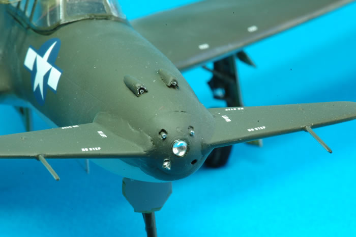
1. Add prominent nose landing light to front tip of fuselage (S/N 278845 had it on the landing gear) (pg. 36 & 55 photos Ginter book) using M.V. Products light lens # 29 (.101” or 2.6mm clear lens).
2. Add two part pitot tube using .042 O.D./.0075 wall stainless steel tubing and a center post using guitar wire placing it on the nose cap.
3. Add stainless steel tubing .025 O. D./ .006 wall for the four gun barrels placing them inside the gun openings. This enhancement might not be technically correct because the full armament load of weapons was only added to XP-55 S/N 278847 but I like the look so I added it.
4. Add an opening for the gun camera to the nose cap below the gun openings and next to the pitot tube. Punch out a clear disc for camera port cover using the left over vac-form canopy mould scrap.
5. Dress up the kit resin gunsight adding the clear reticule. I considered using the Cutting Edge CEC48174 USAAF N-3 Gunsight found during my stash move but saved it for another day.
6. This is not an enhancement but per the instructions, in order to avoid a tail sitter add some nose weight. I listed it so I would not forget! There was a mention of this in the instructions, part #2.
7. Add a brown leather pad to the edge of the control panel overhang.
8. Add a red “T” handle (Parking Brake pg. 42 Ginter book) to the center of the main instrument panel. I used one from a pre-painted Eduard Wildcat etched fret.
9. Add a small rear view mirror to starboard front windscreen vertical support (use photo example from pg. 102 from American Secret Pusher Fighters of World War II).
10. Add a Curtiss Electric 10’ prop logo decal using Fundekals Prop Manufacturers logos decals.
11. Add an antenna wire to the underside mounted mast, and connect the wire to the rear fin tip using E-Z-line. An added enhancement would be to also attach an insulator at both ends.
12. Remove the cockpit air vent on port side of cockpit exterior. The air vent is only found on the first prototype S/N 278845.
13. Add an air flow splitter plate to upper engine air intake (dorsal cowl fin top) near the opening. Some sheet styrene was cut and added to the intake trunking (see pg. 40 Ginter book).
14. Add the rudder actuator and its fairing to the inboard side of both vertical fins of the main wings. I cut a small piece of thin electrical wire with its insulation and cyano glued this to the spot (pg. 57 Ginter book). Once it was dry I built up a teardrop shaped fairing with Tamiya putty. Some careful sanding completed this addition.
15. Add two wing corner formation light using small pearl topped straight pins after painting them Tamiya X-27 Clear Red & X-25 Green to the wing corner formation light positions. Once in place and dry apply clear epoxy to simulate the transparent cover.
16. Cut the vac-form canopy open and construct the folded two part open canopy position using scratch built hinges from a left over Verlinden copper fret.

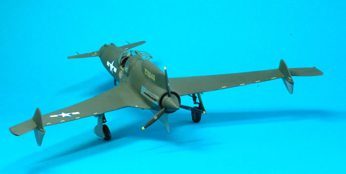
The kit instructions and three-view diagram give the appearance that the two floating stabilizers have a two part pitot shaped extension. It does not, they are streamlined mass balances. A clear forward area picture validates this observation (using pg. 48 & 55 photos in the Ginter book). There was an “L” shaped pitot which is only found on S/N 278845 under the starboard wing. The pitot tube can be clearly seen in the reference book photographs below the lower nose guns.
While setting things up to take pictures I dropped the finished kit due to its very heavy weighted nose. It landed like a lawn dart. It broke the two canard like forward floating wings, with their two poles, the canopy came off and a main landing gear leg snapped near the curved top and has not yet been located despite a desperate search. I attempted fixes and some worked better than others. You might notice some repair patches on the finished kit. This one will not go to any contests!
Cockpit Interior Details
The kit cockpit is better than a rough plastic injection moulded cockpit but once compared to reference photographs it is lacking details. It is a good basis for some additional detailing. I added punched out dials and information warning and data plates from Mike Grant decals CKP 048 “Cockpit Details”. I also used Reheat RH137 Cockpit Placards and Airscale AS48 PLA for additional color placards. Other scratch built components are from styrene sheet and rod with a few copper and guitar wires to represent the throttle and mixture controls levers, seat height lever, parking brake etc.
For example, on the cockpit floor there is a resin part representing the console box on the floor in front of the control stick. The resin has two square boxes in the location that should have two round Oxygen Flow and Oxygen System Pressure Indicators (pg. 41 photos Ginter book). I added some punched out round styrene disks with items from Mike Grant decals with some resin drops to form the warning lights instruments.
Other Additions
I opened the cockpit canopy by cutting the vac-form canopy with a very sharp (i. e. new) hobby knife blade by placing some masking tape as a cutting guide and used part of a spare copper etched metal fret for the canopy hinges. The cockpit had a unique folding opening mechanism (use photos on pg. 88 from American Secret Pusher Fighters of World War II) which I tried to replicate. I used some copper strips from a used Verlinden etched metal fret to form the hinges for the frames to attach them to the main canopy and then to structure the folded portions. I chose the copper rather than the nickel plated Eduard fret material since it seemed more malleable and easier to form. The Fast Frames 41079 vinyl framing was used. It was fantastic on the vac-form canopy giving it an in scale 3D “frame”. I added them after cutting and fitting the canopy. Once on they actually helped as a guide with the final canopy trimming. Despite some criticism they were a novel and useful product if you know how to use them, especially on vac-form canopies. By painting them with the interior color first then the exterior color as a second coat you will obtain a nice interior framing effect once they are applied.
I added wing tip formation lights since none are provided with the kit plastic. I used a saw to cut notches in the wing tips based on photo references. I painted the area with Testors # 1790 Chrome Silver. I inserted the silver pearl tips from clothing straight pins and painted one clear red for the port wing and the starboard wing clear green using Tamiya paints. Once dry I applied some clear epoxy to create the transparent formation light cover found on the actual aircraft.
A final step included adding the natural metal heat shield around the exhaust using Bare Metal Foil.
The kit instructions indicate the topside of the aircraft should be painted Olive Drab, FS34087. I used Tamiya XF-62 Olive Drab FS34087 and Gunze Aqueous H53 Neutral Gray for the undersides. Olive Drab can have a green coloration or sometimes come out with a brown drab coloration. The museum XP-55 aircraft has a definite green coloration and the Tamiya paint seemed to provide the best color match. I was tempted to use Olive Green instead.
I acquired some custom made decals providing the distinctive Curtiss “Ascender” logo seen on the actual aircraft and a few of the prominent stencils such as XP-55-CS Ascender USAAF airframe block stencil,
U.S. ARMY – XP-55-CS
ARMY AIR FORCES SERIAL NO. 42-78846
CREW WEIGHT 200 LBS.
SERVICE THIS AIRPLANE WITH 100 OCTANE FUE
As well as additional stencils for: “GUN CAMERA ACCESSIBLE THRU BATTERY COMPARTMENT” and “ESCAPE PANEL RELEASE”. The kit decals were used for the yellow aircraft serial number, stars & bars and a few white “no push, no handle, push and no step” stencils. It would have been appreciated if the other last digit was included “5” and “7” to allow the building of any of the three prototypes. I wish the kit provided the entire serial numbers for all three prototypes. If there is some reason, due to cost or decal space to not to provide three sets of serial numbers then the 278846 with “5” and “7” as separate numbers on the decal sheet would have been a nice touch. The decals were thin, in register and usable.
The custom decals were provided by Mr. John Brantley at Military Steel Helmets and Decals. His website is: www.military-steel-helmets-and-decals.com. He provided a one week turnaround of the deca
I enjoyed the many kits Squadron released in their range of Czech Model kits starting in 1997. Many fascinating airframes such as the Bell XP-77 lightweight fighter prototype; XP-56 Black Bullet; F3D-2 Skyknight; and FJ-1 Fury are among their releases that I really wanted.
I had a wonderful time building the Czech Model XP-55. The fit of the plastic was good. The details OOB are adequate and results in a fast and simple build. The extras I added and noted in this build were done for increased modeling enjoyment rather than due to gross deficiencies in the base kit. They did not add an excessive amount of extra time to the build cycle.
The base kit and modifications all added up to a most enjoyable project. It actually prepared me for a build of the Czech Model XP-56 Black Bullet. I now regret they never released the Vultee XP-54 and hope someone, if not Czech Model, will someday provide the Vultee XP-54 in 1/48th scale as well! I hope a few re-issues of kits by Czech Model such as the XP-55 would be in the offing from Squadron. They are an excellent platform for extending your modeling skills and adding very unique aircraft to your collection.
References
-
American Secret Pusher Fighters of World War II by Gerald H. Balzer Specialty Press 2008 (XP-55 section - pages 62 – 103)
-
Curtiss Ascender XP-55 by Gerry Balzer 2014 (Ginter Books # 217 - Air Force Legends series)
Note:
There is a Curtiss XP-55 Ascender restored by The Air Zoo. It is a museum located at 6151 Portage Road in Portage, MI, halfway between Detroit and Chicago, USA. The Air Zoo received the XP-55 Ascender on loan from the Smithsonian National Air & Space Museum in exchange for a restoration. On loan from the Smithsonian National Air & Space Museum, The Air Zoo has the only surviving XP-55 Ascender! It has been beautifully restored for the NASM by the Kalamazoo Air Zoo restoration department. It looks wonderful in its display.
Model, Images and Text
Copyright ©
2014 by Andrew Garcia
Page Created 17 September, 2014
Last Updated
17 September, 2014
Back to HyperScale Main Page
|
 Home
| What's New | Features | Gallery | Reviews | Reference | Resource Guides | Forum |
Home
| What's New | Features | Gallery | Reviews | Reference | Resource Guides | Forum |