Meng's 1/48 scale
P-51D Mustang
Part Two - Construction
|
|
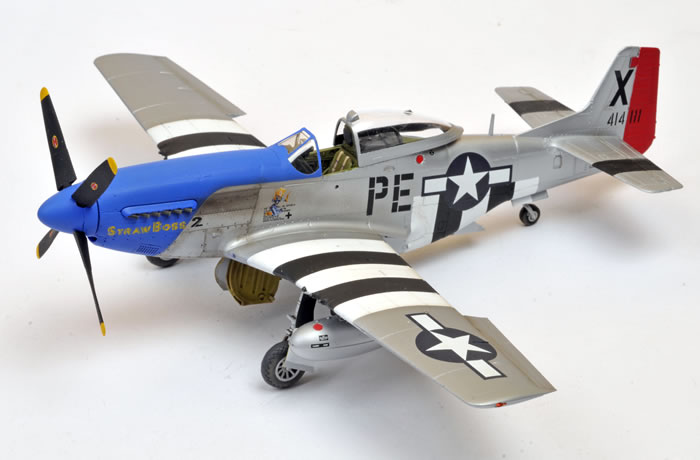
Noth American P-51D Mustang |

Meng's 1/48 scale P-51D Mustang will be available online from Squadron
Last week I reviewed Meng's forthcoming 1/48 scale P-51D Mustang on HyperScale.
In this instalment, I build the model.
Three Things Meng’s Mustang Is Not... |
Before I start describing construction, I would like to point out three things that the new Meng 1:48 scale P-51D Mustang is not.
1. It Is Not a Beginner’s Kit
Despite its cement-free status, this is not a kit that I would recommend for an absolute beginner. Meng’s Mustang includes a number of small parts and a series of inserts, especially on the fuselage and wings. Also, the parts count is not small - 103 grey plastic parts compared to only 55 in Tamiya’s original 1:48 scale P-51D release. It won’t present many challenges for anyone with a couple of models under their belt, but I’d recommend an Egg Plane rather than this one for the genuine first-timer or younger modeller.
2. It Is Not a Simplified Kit
Cement-free does not imply lack of detail. On the contrary, detail is excellent. In my opinion Meng’s Mustang offers the best cockpit detail and surface textures of any 1:48 scale P-51D currently available. In a number of respects (fuselage and wing parts breakdown, wheel well engineering, surface detail), Meng’s kit reminds me more of Tamiya’s 1:32 scale Mustang than their 1:48 scale version.
3. It Is Not a Gimmicky Kit
The large, tight fitting locating circles are more than a gimmick. They do help with the alignment of parts. I especially liked this method of assembly for the wings. The engineering of the kit is so good that you really don’t need to apply glue for the major assemblies but I generally ran a line of Tamiya Extra Thin Liquid Cement along most of the join seams anyway.
A real benefit of the press-fit parts is that it eliminates the need for masking in some commonly troublesome areas. The fit is so precise and tight that, for example, the wheels and tyres may be painted separately and pressed together during final assembly – no masking or messy glue required! The same applies to the propeller blades and the two-piece spinner cap and base.
Experienced modellers need not be ashamed to be seen buying and building this kit.
Suggested Deviations From The Instructions |
For the most part I followed the instructions, but I deviated in a few areas, and I would do things differently next time in a few others. The suggestions below are provided in the order of the kit instruction steps. In summary:
Instructions Step 1
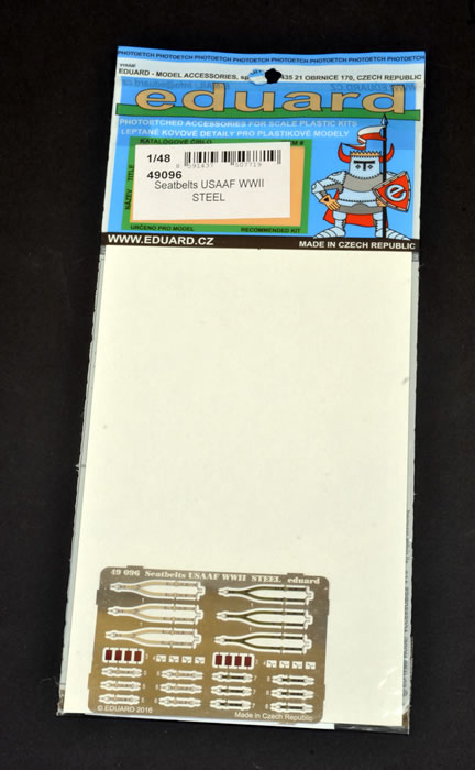
I added Eduard “Steel” harness straps. I also used MDC individual instrument dial decals as I did not think the overall instrument panel decal supplied in the kit was up to the same high standard as the rest of the cockpit.
Instructions Step 3
I did not attach the tyre (Part E2) to the tail wheel strut yet. I actually tried to find a way to leave the strut off until later in construction, but I was not confident that I could fit it without removing detail from the part so I went with the instructions.
Instructions Step 4
I delayed fitting the exhausts until painting was finished.
Instructions Step 5
I fitted the rear upper fuselage insert (Part C5) at this stage. The instructions would have you fit this spine saddle insert after the canopy is fitted, but I did not want to have the canopy on the model during painting. This meant that I had to sacrifice the sliding canopy feature, but I was not concerned about this.
I had a little trouble getting perfect alignment between the bottom edges of the spine saddle insert and the main fuselage. Next time I will probably cut off the stout tabs moulded to the fuselage. This will allow easier adjustment of the spine saddle insert.
I fitted the aerial mast at this time too. As supplied, it is pushed through a hole from the inside of the saddle insert. The problem with this is that the delicate mast is exposed through the bulk of construction and all of the painting stage. Inevitably, I knocked the top of the mast off during assembly. Next time I will modify the mast so that I can simply stick it on the spine after painting is complete.
Instructions Step 6
I did not fit the undercarriage legs at this stage. I was worried that I would damage the legs during assembly or painting. Also, the dangling undercarriage legs would make masking the wheel bay more difficult. I found that I could fit the undercarriage legs after painting was complete by cutting a wedge from the top of the right-angle section of the locating tab (see photo below for more detail).
Instructions Step 8
I attached the wing to the lower fuselage before adding the lower engine cowling insert.
Instructions Step 11
Next time I would not fit the drop tank sway braces (Parts B23) until just before the drop tanks were fitted. These parts are tiny and delicate. Two of mine disappeared during masking and painting.
Instructions Step 12
I planned to cut off the two raised pins at the bottom of the canopy centre guide to permit the part to fit into the slot on the fuselage spine. In fact, I accidentally broke the centre guide off so I simply glued the canopy in the open position.
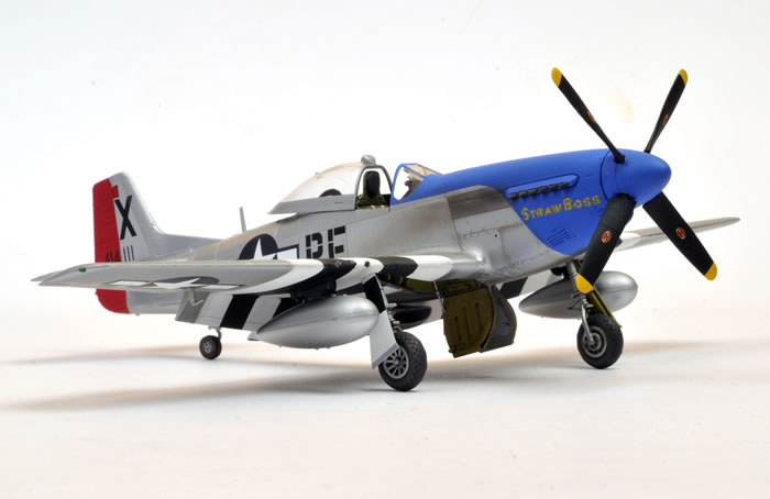
Markings
I used markings from an old Eagle Strike decal sheet Item No. IP4807, "Blue Nose Birds of Bodney in Profile Part One". I'd been looking for an excuse to use these markings for years!
Construction is described step-by-step in the accompanying captioned photos.
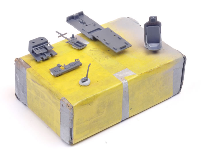
Cockpit components were cut from the sprues and cleaned up.
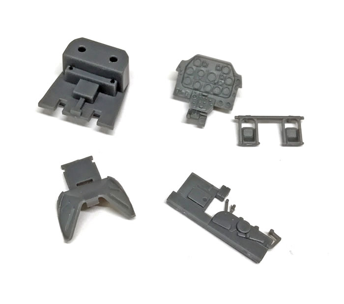
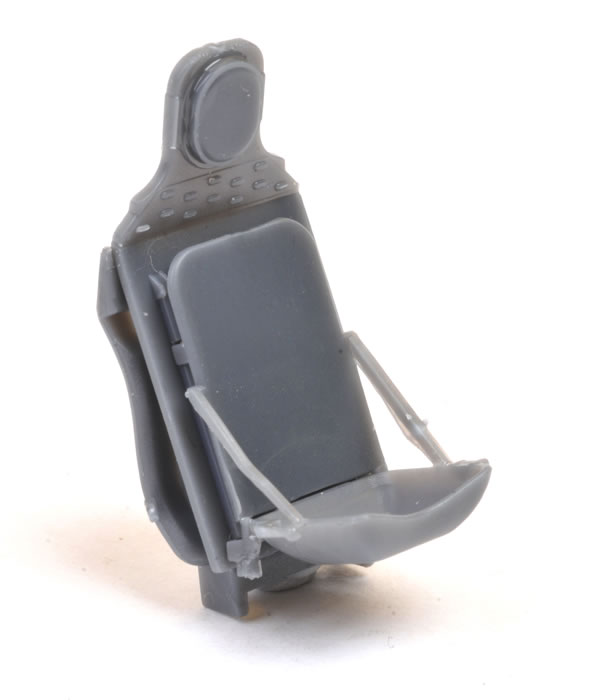
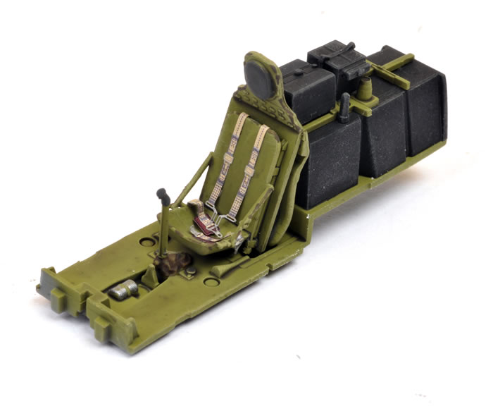
The six parts of the well-detailed pilot’s seat.
Cockpit floor, fuel tank and details.
The six-piece seat assembled.
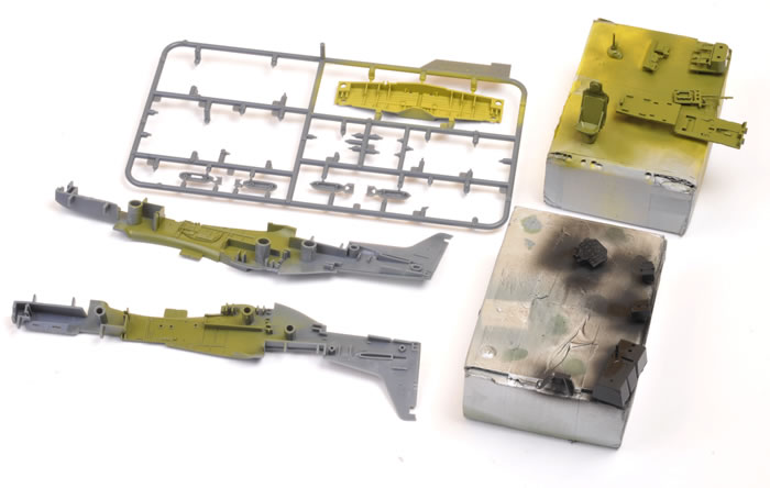
Parts were separated into groups depending on their ultimate colour and attached to small boxes using Blu-Tack, ready for paint.
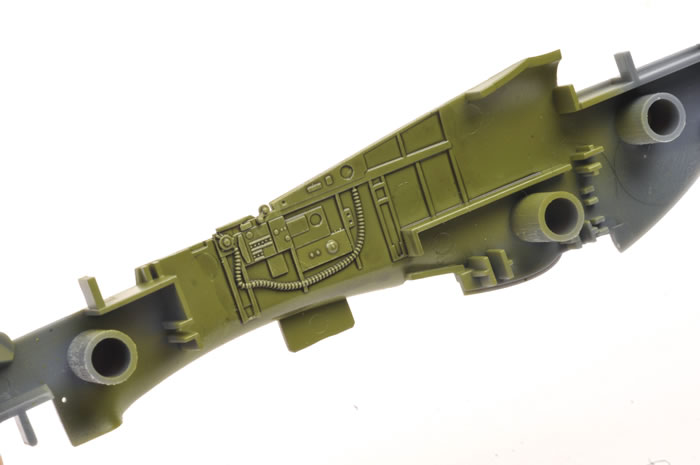
The fuselage interior was painted at the same time, and the main undercarriage bay was sprayed while still on the sprues.
Detail is moulded onto the starboard cockpit sidewall. A separate throttle quadrant panel is supplied for the port side.
Tamiya XF-1 Flat Black, XF-64 Red Brown, Future Floor Polish and water was mixed into a thin wash.
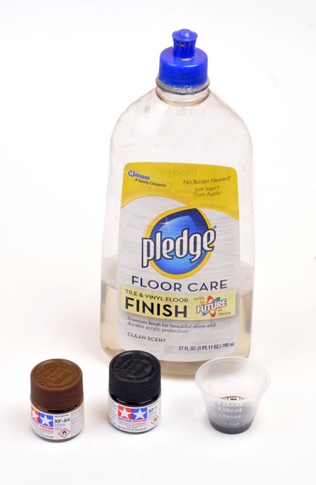
The wash was applied over the raised cockpit detail. This is fast, easy and very effective.
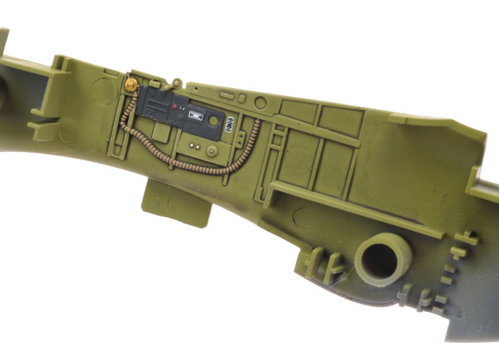
Here, details have been picked out with Vallejo acrylics and a fine brush. A top coat of Alclad II Flat Clear has also been applied.
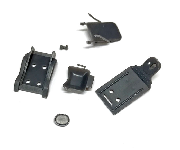
The kit does not include harness straps so I used a set from Eduard’s Item No. 49096 “Seatbelts USAAF WWII STEEL” set. The STEEL series straps are very thin and highly flexible, contrary to what the name implies!
Cockpit floor sub-assembly with paint, weathering and flat coat.
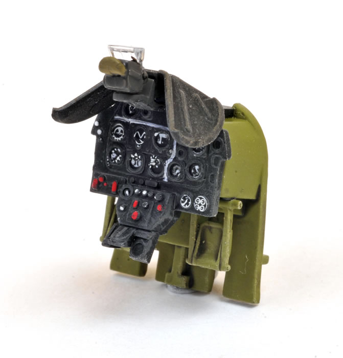
Instrument panel and rudder pedal sub-assembly with coaming. I used MDC instrument decals for the individual dials. The white lines are hand painted.
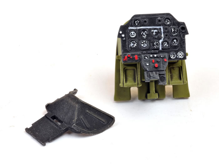
Coaming and gunsight attached.
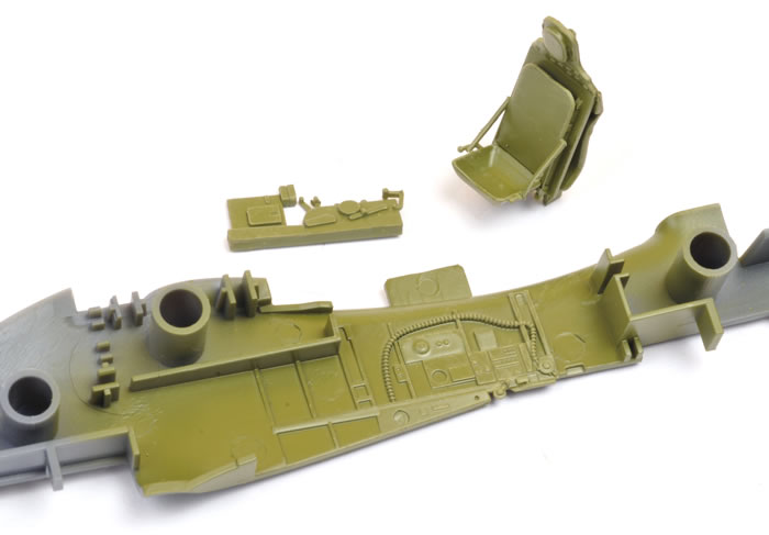
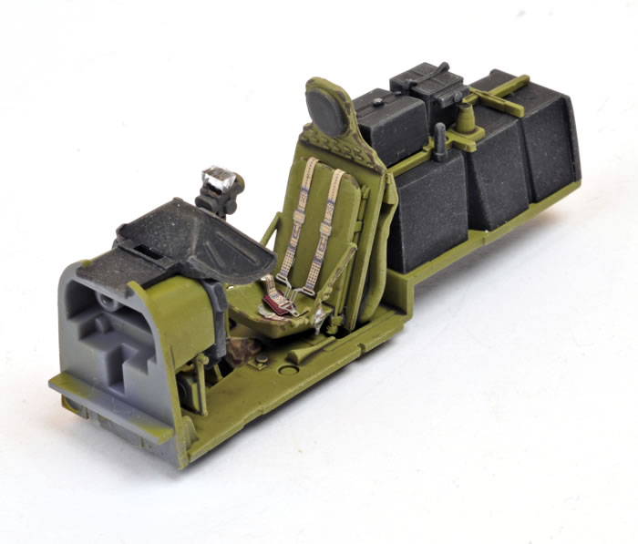
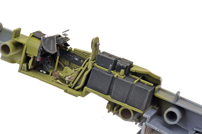
The main cockpit sub-assemblies come together.
Detail is well done straight from the box.
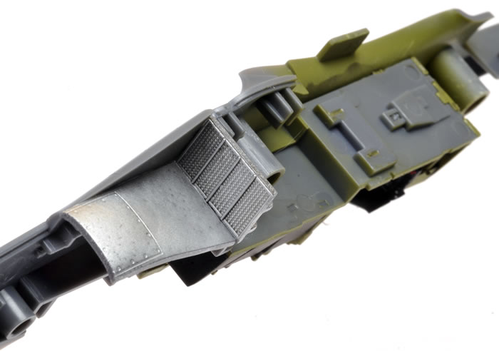
Trailing radiator face detail.
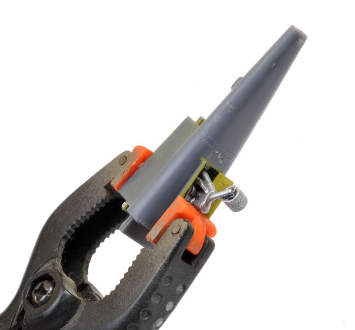
There is no way to avoid installing the tail wheel strut at this stage, but you don’t have to fit the tyre.
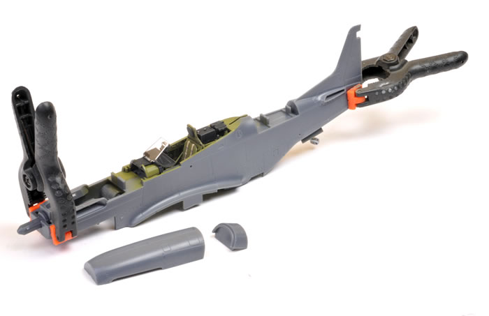
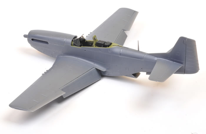
Interior parts are fitted. The fuselage halves are now ready to be pressed together.
The fuselage halves were squeezed together. A line of Tamiya Extra Thin Liquid Cement was brushed along the join seams and the parts clamped (just for insurance).
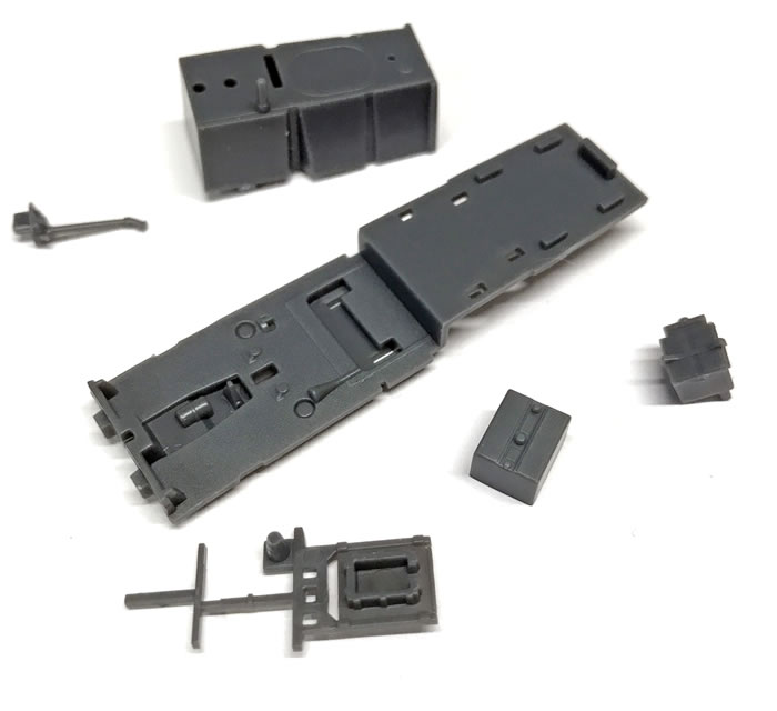
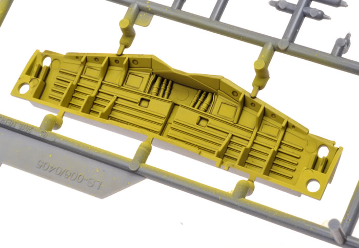
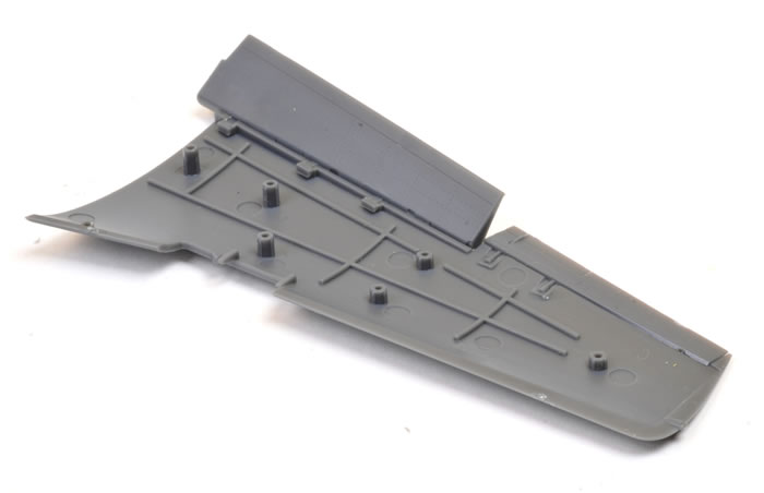
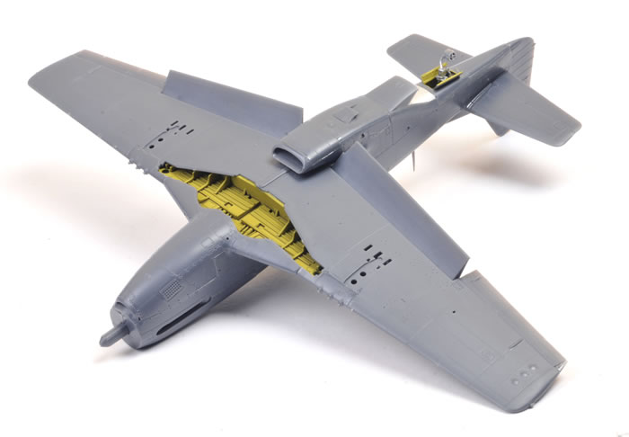
The weathered main undercarriage bay about to be snipped off the sprue. Unlike most 1:48 scale P-51D wheel bays, this is the correct shape.
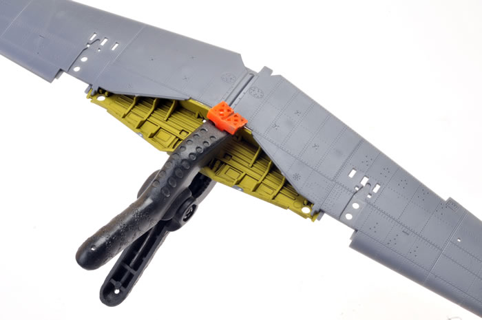
Once again, I used glue to make the bond between the wings and the undercarriage bay permanent.
Flaps and ailerons were glued in place (once again, for my own sense of security rather than necessity) and the upper wing halves pressed into place.
Gluing the control surfaces ensured that they stayed in the right place as the wing halves were brought together.
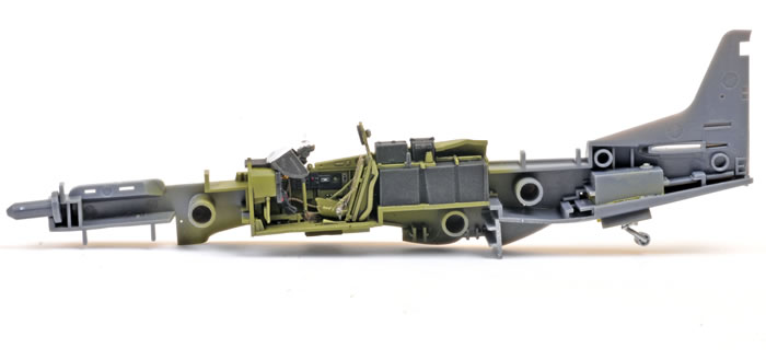
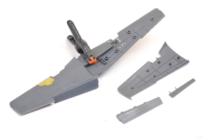
The fuselage and wing assemblies are complete.
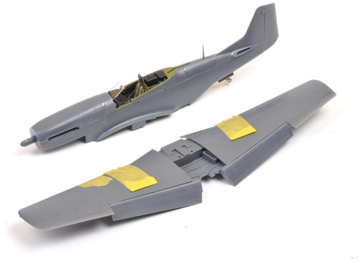
The wing was attached to the fuselage.
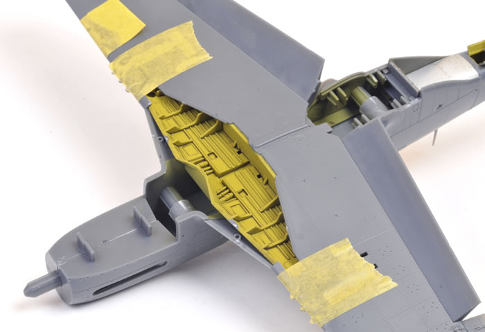
The lower cowl insert came next, followed by the radiator intake.
Fit was excellent throughout. Wing roots, the lower cowl, radiator insert and the two upper cowl parts were close to perfect. I had some trouble lining up the lower edges of the upper rear fuselage saddle insert with the fuselage sides, but a little scraping and sanding took care of that.
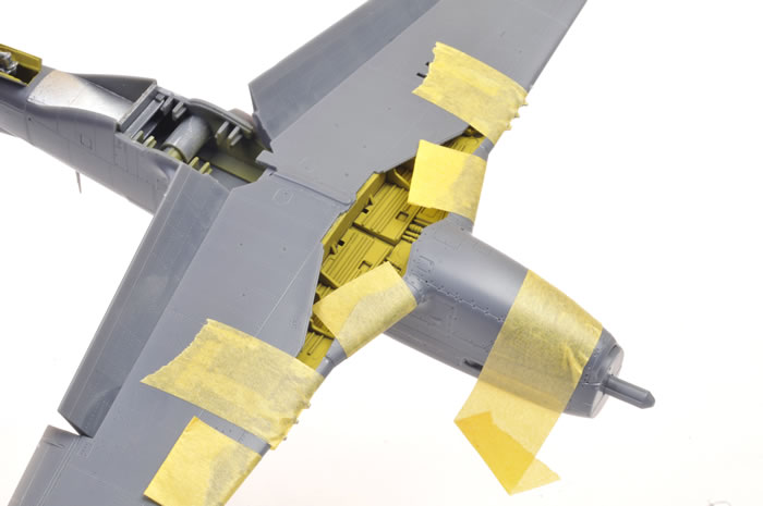
Extraordinary fit on the lower surfaces.
I found that I could fit the undercarriage legs after the wing was assembled by cutting a wedge from the right-angle mount at the top of each leg.
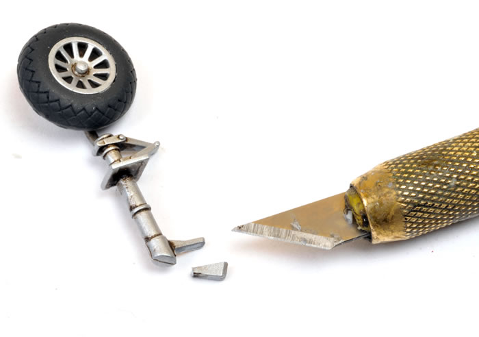
The fit was still quite tight without adhesive. I glued the legs in place once I was satisfied with the rake and the splay.
Another point worth mentioning is that the canopy should sit down on the fuselage when open, and not have the tail-up attitude that we see here. I checked the fit in a number of positions but the kit canopy sits high either at the front or the rear depending on how it is fitted. If this bothers you, the easy solution would be to fit a Falcon vacform canopy (or you could simply pose the canopy closed!).
Meng has taken an interesting and different approach with their new 1:48 scale P-51D Mustang.
This may not be an ultra-simple kit for beginner modellers, but its glue-free approach offers a number of advantages to the average and experienced modeller in terms of positive fit and reducing the need for masking. Detail is very good, surface textures excellent and engineering is clever throughout.
I have read a number of complaints on HyperScale's Plane Talking Forum about the rivet detail on the wings (P-51D Mustangs were delivered puttied and painted from the factory), but there were undoubtedly Mustang wings that had been stripped in the field, and it will be easier for modellers to fill the recessed rivets than add rivets for those who do want the surface detail.
Regardless of its glue-free status, in my opinion Meng’s P51D has now snatched the title of best 1:48 scale bubbletop Mustang available today.
Building the kit only reinforces my first impressions of quality and fidelity.
Model, Images and Text
Copyright © 2016 by Brett Green
Page Created 7 November, 2016
Last Updated
8 November, 2016
Back to HyperScale Main Page |
 Home
| What's New | Features | Gallery | Reviews | Reference | Resource Guides | Forum |
Home
| What's New | Features | Gallery | Reviews | Reference | Resource Guides | Forum |