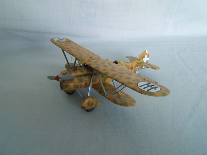
Special Hobby's 1/48 scale
Fiat CR.32 Freccia
|
Fiat CR.32 Freccia |
by Michael Rohde

Hobby Boss's 1/48 F4U-7 Corsair is available online from Squadron.com
The CR.32 prototype took to the air for the first time on 28 April 1933.
Due to the superb design work by Celestion Rosatelli and his design team, the CR.32 was an instant success and first production orders were received in March 1934.
The type soon equipped the No 1,2 , and 4 stormi of the Regia Aeronautica.
Series aircraft were equipped with variable pitch propellers and had provisions to carry a radio transmitter/receiver, a panoramic camera or bomb racks.
Modified versions of the CR.32 were built up to 1939, each variant designed to reduce all up weight and improve performance.
In addition , the CR.32 was demonstrated widely abroad and attracted considerable export orders.
During the Spanish Civil War the CR.32 was used extensively in operations supporting the Nationalists and soon gained a reputation as one of the outstanding fighter bi planes of all time.
At least 380 took part in the air battles over Spain, providing formidable adversaries to the Polikarpov I -15 bi planes and I- 16 mono planes which formed the back bone of the Republican fighter arm.
CR.32s were used for numerous aerobatic displays, many of them in Italy.
During 1936 displays were given also in many European capitals and major cities and in 1937 throughout South America.
The Italian team's ( No 4 stormo regia Aeronautica) return to Europe culminated in a brilliant display in Berlin.
The remarkable aerodynamic characteristics of the CR.32 and its undoubtable success in Spain misled the Italian Air Ministry to support the view that biplanes still had potential as a weapon of war with the result that the Fiat CR 42, a development from the CR.32, was already an outdated concept before the prototype made its first flight.
So it came to be that the CR.32 itself soldiered on into WWII , and when Italy declared war in June 1940, 325 CR.32s were still in front line service.
Some were adapted as night fighters, while those operated by units in Libya were largely used in ground attacks against British troops.
The greatest war time successes achieved by CR.32s were in Italian East Africa, aircraft of the 410a and 411a Squadraligia destroying a number of British and South African aircraft before the final Italian surrender in that theatre.
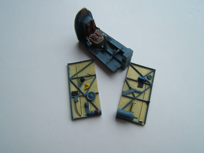
Special Hobby has provided us with a multi-media kit consisting of 32 plastic parts molded in grey plastic ,1 clear part ( windscreen), 22 resin parts and 2 sheets of photo etch.
The plastic rudder and tail plane bits are to be replaced by the resin parts provided. The cockpit section is made entirely of resin parts.
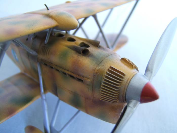
The forward fuselage section is one solid resin piece with nicely moulded detail.
The photo etch sheets give us seat belts, instrument panel ,rudder bar, various levers and the aileron stabilizers. To do the CR.32 'quater' variant an extra oil cooler and 2 bombs and racks are provided in resin.
Unfortunately Special Hobby has the habit of putting their resin parts into plastic bags without protective wrapping and in this case the forward fuselage is especially vulnerable because of the finely molded cooling fins and the fluted muzzle tubes. I had to repair some of these details.
Another defect was found on the tailplane and rudder – they had air bubbles which needed to be filled and cleaned up.
The decal sheet gives us four options:
-
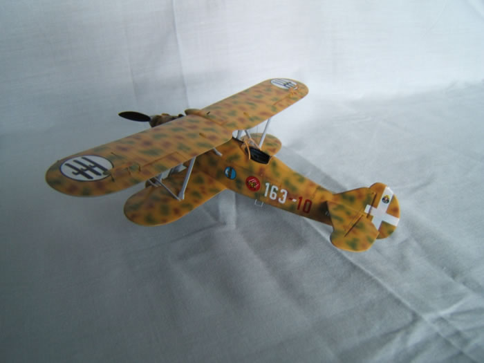
163-10 M.M.3518 163 Squadraligia Rhodos June 1940
-
160-10 M.M. 4666 160 Squadraligia 12 gruppo 50 Stormo d' Assalto Tobruk 1940
-
V 105 1/1 squadron ( 'the archer') Hungarian Air Force 1939
-
3-61 (C. No. 11) Esquadrilla 2-E-3 Aviacion Nacional Zragoza ( Spain) 1939
The first step was to prepare all the resin parts ( except bombs and racks) and paint these according to the instructions. Please note : the cockpit floor sits right on top of a substantial resin block. But a bit of trimming back the bottom part and dry fitting into the fuselage halfes ensured a snug fit. So there is no need to separate the cockpit floor.
At this stage I did the surgery necessary to fit the resin rudder and the resin tail plane.
This also required holes to be drilled where indicated on the rear fuselage to accommodate the locator pins on the resin tail plane.
Then I moved on to fit the starboard cockpit side wall and rear bulkhead (with the seat attached), attached all the photo etch seat harnesses and the rudder bar followed by the port sidewall.
A final check of the complete cockpit tub assembly fitting into the fuselage was done at this stage.
The photo etch instrument panel was installed and the whole assembly was finally glued into the right fuselage shell with CA glue.
Now it was time to close up the fuselage ,clean up the seams and prepare for the next step: Fitting the front part of the fuselage .
Again ---this part (the engine and oil cooler) was attached to another rather substantial resin block. First I thought it would be necessary to separate the forward fuselage frome its resin base but then I had the idea to simply try and trim back the out line of the resin base and see if I can fit the whole block into the fuselage. And-- hey presto-- , this came along quite nicely and saved me a lot of time. The interface between resin and plastic panels was actually quite precise and needed very little adjustment.
I did carry out the repairs mentioned earlier before I dry fitted the whole assembly.
Before I continued I protected the fragile cooling fins and the muzzle tubes with masking tape to avoid any further damage.
Now it was time to fit the lower wings and the tail plane ( incl elevators and rudder.)
Beware! The lower wings do not have any locating pins and the interface of both fuselage and wings are not even. To minimise gaps it was necessary to trim back material in small increments in these places to achieve a better fit.
The wings were glued into place and the correct angle was checked repeatedly until the glue had set( no dihedral!). Tamiya filler was used to remedy any gaps remaining and leading and trailing edges were carefully sanded to remove flash.
Pretty much of the same applied to the resin tail plane. For starters the locator pins had to be shortened somwhat so not to interfere with the opposite part and careful trimming the resin interface was needed to ensure a good fit . Remaining gaps were minimal and easily fixed with a bit of CA glue and some sanding.
The elevators were glued into their respective recesses and the supporting struts attached. Then the rudder and the rudder linkages were set.I only use the actual bars and replaced the cables with EZ line ( the P/E is just too delicate and easy to bend ).
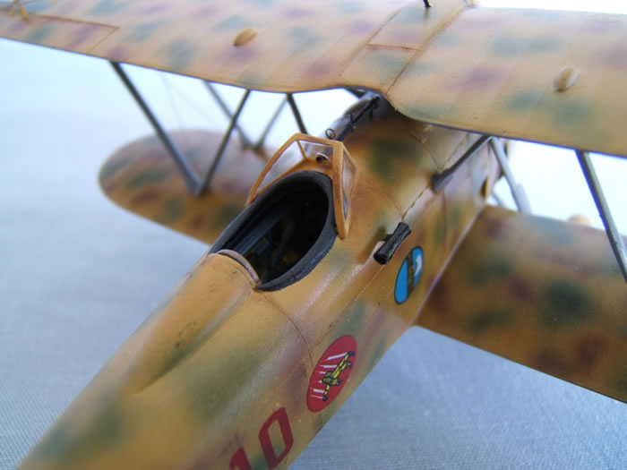
At this stage I decided to test fit the wind screen and made adjustments to ensure the best possible fit on the fuselage. There is no opening for the telescopic gunsight and a small hole had to be drilled into fhe front panel to accommodate the tube.
The gunsight is also made of resin and a P/E ring and bead sight have to be installed onto the tube as well. After I glued the windscreen to the fuselage decking I fed the gun sight through the hole to get an idea how this part has to be placed. A small piece of Evergreen strip was glued to the front part of the gunsight as a support. I left final ring and bead and telescopic gunsight installation for later. (Too fragile to install at this stage).
The next steps ( fitting the landing gear and attaching the struts in a W shaped arrangement) were made easier with the help of a reference book with accurate 1/48 scale drawings. There are markings on the wings to indicate the attachment points , but- as a matter of fact- these are not correct.They are a bit too far apart . The attachment points are closer together!
Before I continued I cleaned up the upper wing by removing flash on the leading and trailing edges with careful sanding and polishing. All the struts ( incl the cabanes and the four small support struts underneath the upper wing tank needed a lot of work to begin with. .Pretty much all of these( except the smallest ones) had sinkmarks and needed fixing .
That done the difficult part started.We have to get the angle and position of the struts right for starters. I used a compass to measure the width of the cabane struts on the drawings and then I glued these into place on the upper fuselage decking. While the glue set I drilles small holes into the bottom part of the center tank where the small support struts were supposed to go according to the drawings. The same was done on the upper fuselage decking.
I decided to insert the small struts later once the upper wing was in place.
Next I glued the 8 large struts onto the lower wing. Again – measuring the spread was important to get the angle right.
When the glue had set I attached the upper wing to a stiff piece of cardboard using some strips of masking tape.
Then I placed the fuselage/ lower wing assembly onto the upper wing to check the alignment and how big the difference ( gaps)was between struts and their respective attachment points. I tried to get these as even as possible by removing small amounts of material .All that was done by constantly checking the angles and alignment of the fuselage / lower wing in relation to the upper wing.
Finally -being satisfied with this positioning business- I moved on to attach the landing gear struts.
I had to refer to the drawings in that reference book to find the exact location of the attachment points. Small recesses were drilled to help locate the struts. The Special Hobby instructions were not precise enough!
Prior to this step the wheels and the inside of the spats were painted and assembled. The V shaped inner landing gear struts were glued to the spats first ( the right angles were easily identified refering to the drawings in the book.) Then these parts were glued into place and the main supports were attached at the same time. Constant checks were necessary( until the glue had hardened sufficiently) to assure proper alignment of the whole structure. Needless to say that some filler was necessary to get rid of some gaps between the wheel spats and the struts.
I must say that this operation was( together with the upper wing ) one of the most demanding actions I have experienced in all these years building models. Not for the faint hearted!
This was a good time to drill the tiny holes on the lower wing and tail plane necessary for rigging the outer struts except the holes on the upper wing.These were easily done after the installation of the upper wing ( due to the much shorter wing span of the lower wing )
Holes for the installation of the aileron stabilizers ,aileron linkages and their respective control cables were drilled as well.
The reason to do things in that sequence was because it was easier to airbrush the the upper wing as a separate item ( small patches of masking tape covered the spots where the struts had to be glued into place.). If one decided to go as per instructions there would have been very little space between upper fuselage and upper wing center section to do any proper airbrushing.
Further painting followed accordingly : all undersides and struts painted sky gray( Tamiya XF 11)
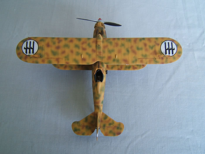
Mottled camo scheme was done Humbrol 160 ( red brown) Humbrol 30 ( dark green) and Humbrol 63 ( sand) with an overall clear gloss coat .
Having given the paint a good 24 hours to cure it was time to fit the upper wing.
I removed the small patches of masking tape frome where the struts were to be glued to the wing and removed paint from where the contact areas between struts and wing surface are.
The upper wing was re attached to the cardboard jig and the fuselage and lower wing assembly was aligned with the upper wing and secured with masking tape to avoid any movement while applying the CA glue.
All went well and any remaining gaps were filled with CA glue and left to cure overnight.
The area around the attachment points were carefull touched up with a small brush using Tamiya XF 11 skygray and left to dry.
The aileron stabilizers were painted separately and glued into place together with the aileron cable linkages. Not to forget the auxiliary ring and bead to be fitted on the telescopic gunsight.
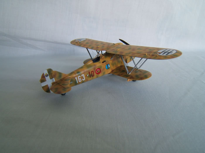
Now it was time to apply the decals . In this case I have chosen the decals for aircraft 163-10 --163 Squadraligia. Rhode June 1940.
A thin coat of clear gloss was used to seal the decals.
The final step to finish the model was to use EZ line for the outer struts and tail plane rigging and the cable linkages to the elevators and ailerons.
A fine example of a famous 1930's Italian bi plane fighter by Special Hobby.
Not an easy build by any means but well worthwhile the effort and a nice addition to my interwar period collection of aircraft models.
Recommended to everybody with some experience in building multi media kits.
Text and Images Copyright ©
2019 by Michale Rohde
Page Created 13 January, 2020
Last Updated
13 January, 2020
Back to
HyperScale Main Page

|
 Home
| What's New |
Features |
Gallery |
Reviews |
Reference |
Forum |
Search
Home
| What's New |
Features |
Gallery |
Reviews |
Reference |
Forum |
Search